Display_Touch_LVGL: Arduino 5.0-inch ESP32-S3 Environment Monitoring and LED Control
1. Course Introduction
This lesson uses the Arduino framework, LovyanGFX, LVGL 9.1.0, GT911, and DHT20 to drive the CrowPanel 5.0-inch 800×480 RGB display. After the program starts, it shows the environment monitoring interface generated by SquareLine Studio; tapping the ON/OFF button toggles the LED on GPIO38, the DHT20 updates the temperature and humidity labels every second, and the serial port outputs the touch coordinates and sensor status.
Learners need to complete board setup, project compilation, and upload, then observe the LCD, touch, LED, and serial output. At the end of the lesson, eight standalone examples are also provided—covering LED, speaker, SD card, touch, BLE, Wi-Fi, and GPS—to help verify the onboard or external functions one by one.
Reference materials:
2. Learning Objectives
- Be able to explain the data flow among the 800×480 RGB display, the GT911 I2C touch, the DHT20 I2C sensor, and the LVGL callbacks.
- Be able to select ESP32-S3, OPI PSRAM, and the correct serial port in the Arduino IDE, then compile and flash the main lesson project.
- Be able to determine whether the display, touch, LED, and temperature/humidity chain are working correctly by means of the touch button, the serial log, and the on-screen labels.
3. What You Need to Prepare
- CrowPanel ESP32-S3 5.0-inch HMI (800×480 RGB display, GT911 touch, DHT20).
- A USB-C data cable that supports data transfer, and a computer.
- One DHT20 temperature and humidity module, connected to GPIO19 (SDA) and GPIO20 (SCL).
- One LED module, connected to GPIO38.
- Arduino IDE 2.x, ESP32 Arduino Core 3.3.0 or a compatible 3.x version.
Arduino/librariesinside the project: LVGL 9.1.0, LovyanGFX, PCA9557, Crowbits_DHT20, and the GT911 library; do not install a different version that would overwrite the project libraries.- Fully preserve the
ui*.c,ui*.h, and image array files in theLVGL_Arduino5.0directory; do not copy only the.inofile.
4. Software Operation Steps
This tutorial uses Arduino IDE 2.3.10 for demonstration. The IDE version is not strictly required; other versions work as well.
For the first attempt, complete the steps in order; do not skip directly to upload after a build failure.
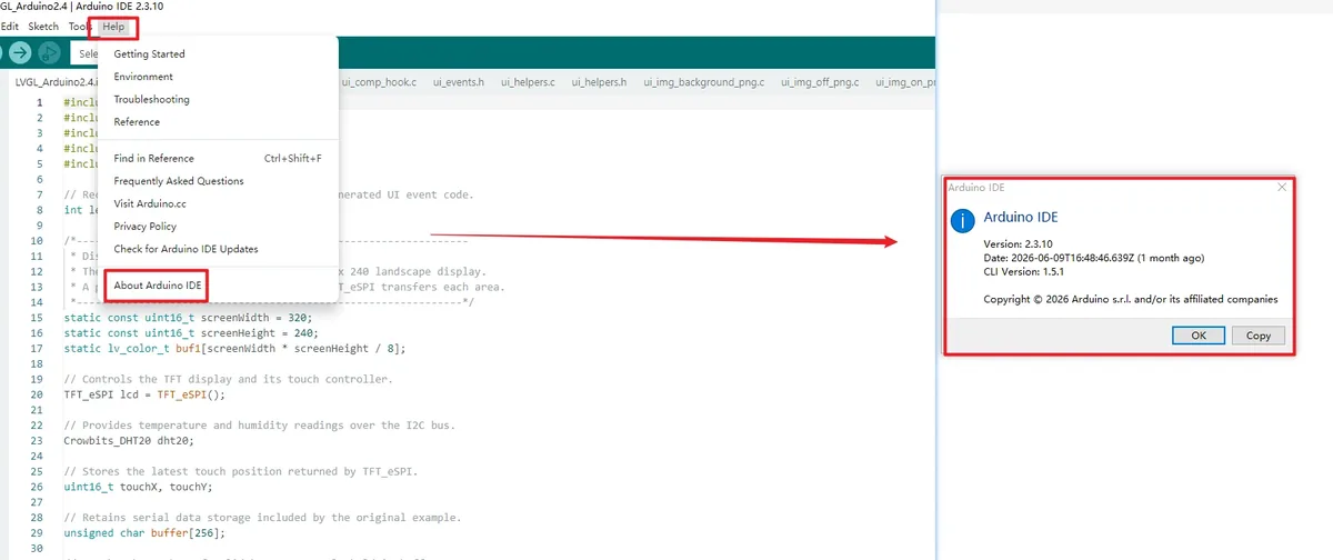
Launch the Arduino IDE, open Help > About Arduino IDE, and confirm the version is 2.3.10. Close the About window before continuing.
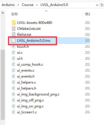
Enter the project folder LVGL_Arduino 5.0, and open LVGL_Arduino5.0.ino. The window title should show the project name.
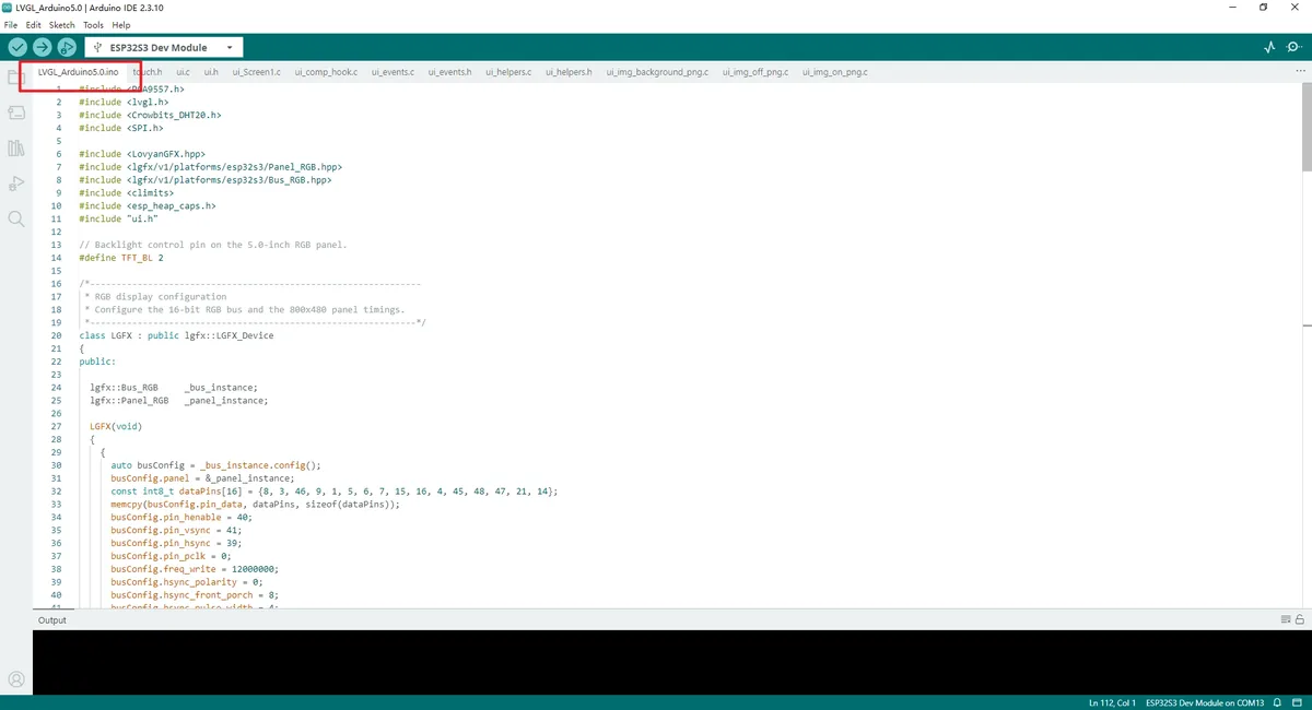
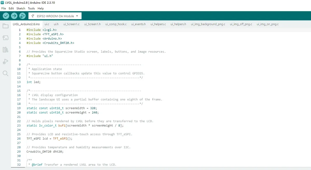
Check the file tabs above the editor area and confirm that ui.c, ui.h, ui_Screen1.c, and three ui_img_*_png.c files are visible in the same project. If these files are missing, do not continue compiling; instead, copy the complete project directory again.

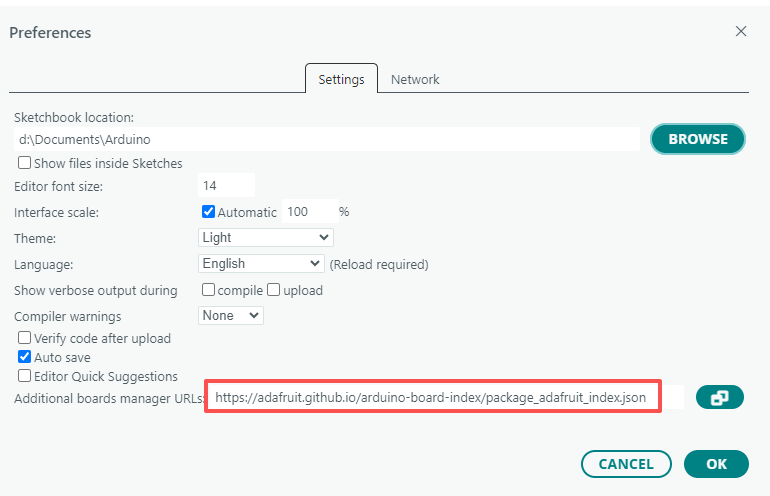
Open the Arduino IDE and go to File > Preferences.
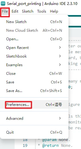
In Additional boards manager URLs, add the Espressif ESP32 board index address:
Remember to click confirm after making changes.
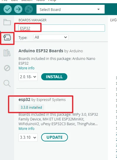
Open the Boards Manager, search for esp32. Find esp32 by Espressif Systems, select and install 3.3.8; if the interface already shows 3.3.8 installed, close the Boards Manager directly.
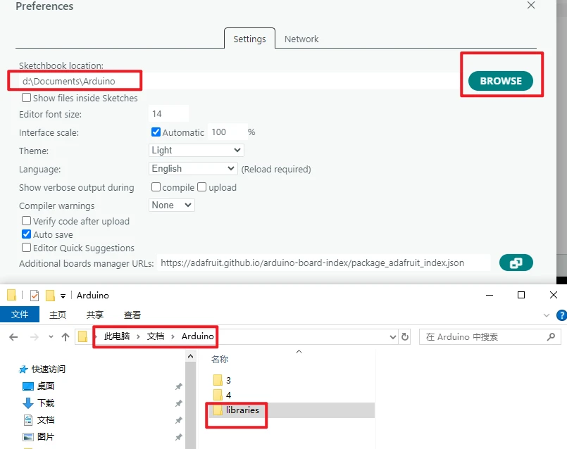
Open File > Preferences, and note the "Sketchbook location". Close the Arduino IDE, then confirm that the libraries folder exists in that directory.
How to add the library files: https://www.elecrow.com/wiki/Arduino_IDE_Library_Import_Guide.html.
Note: The course dependency libraries need to be placed in the libraries directory under the Arduino sketchbook folder. After copying, restart the Arduino IDE to prevent the IDE from using the old library index.
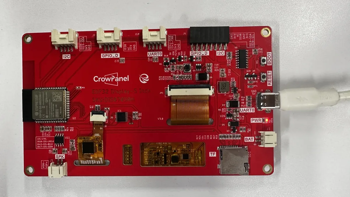
Connect the board with a USB data cable.
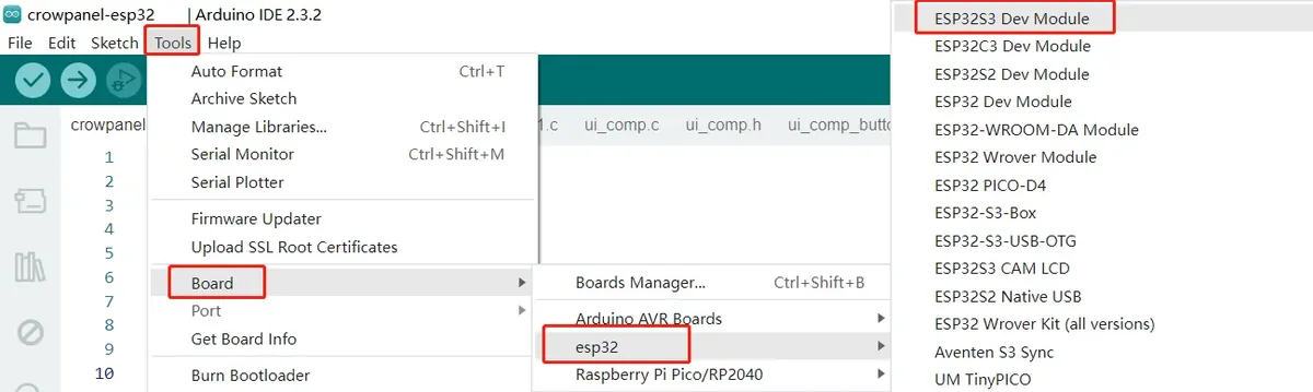
Open Tools > Board > esp32, and select ESP32S3 Dev Module. After that, the IDE top bar or status bar must show ESP32S3 Dev Module.
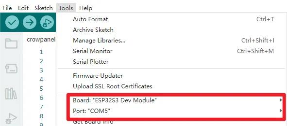
Open Tools > Port, and select the COM port that newly appears after connecting the board. If no port appears, first replace the USB cable with one that supports data transfer, then check the serial port status in the system Device Manager.
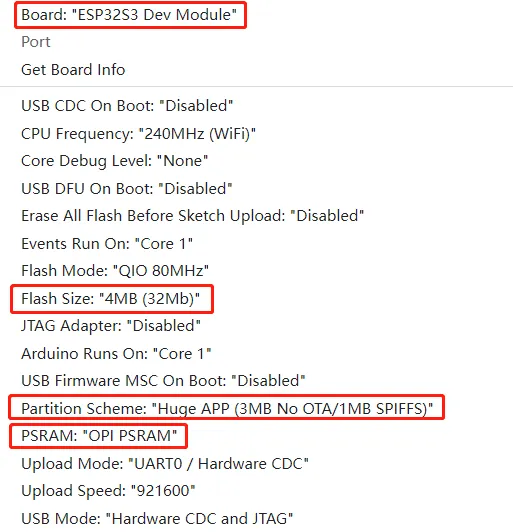
In the Tools menu, set Flash Mode: QIO 80MHz, Flash Size: 4MB (32Mb), Partition Scheme: Huge APP (3MB No OTA/1MB SPIFFS), and PSRAM: OPI PSRAM; leave the other options at the default values used when the project was verified.
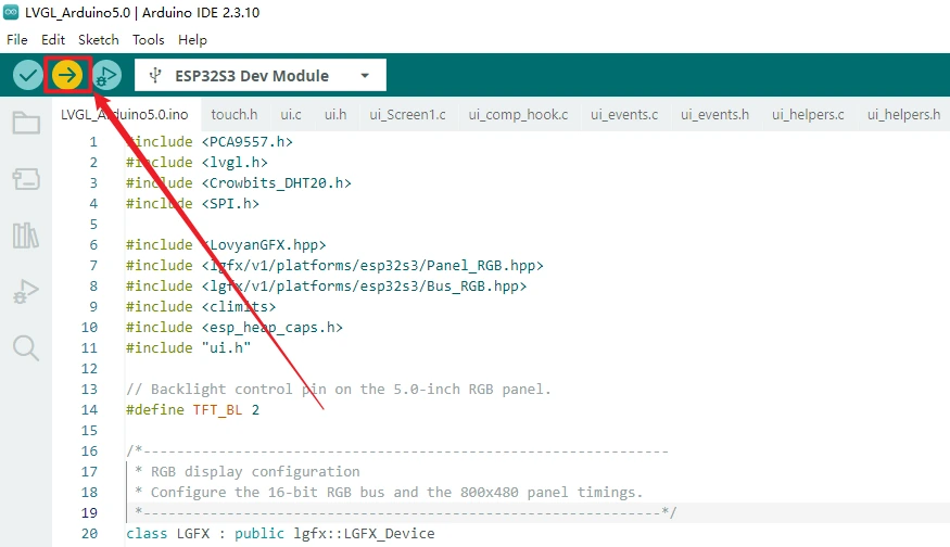
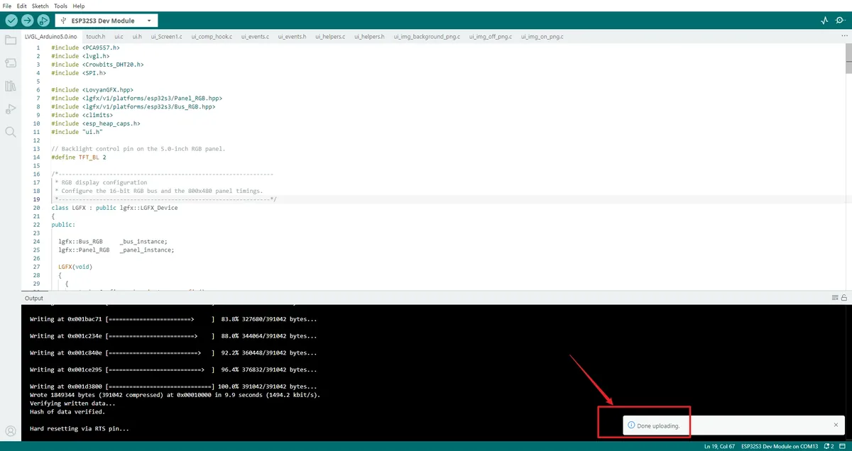
After verification succeeds, click Upload and wait for the write progress to reach 100%. If it stays at Connecting... for a long time, hold the board's BOOT button, release it after writing begins, then recheck the port and upload mode.
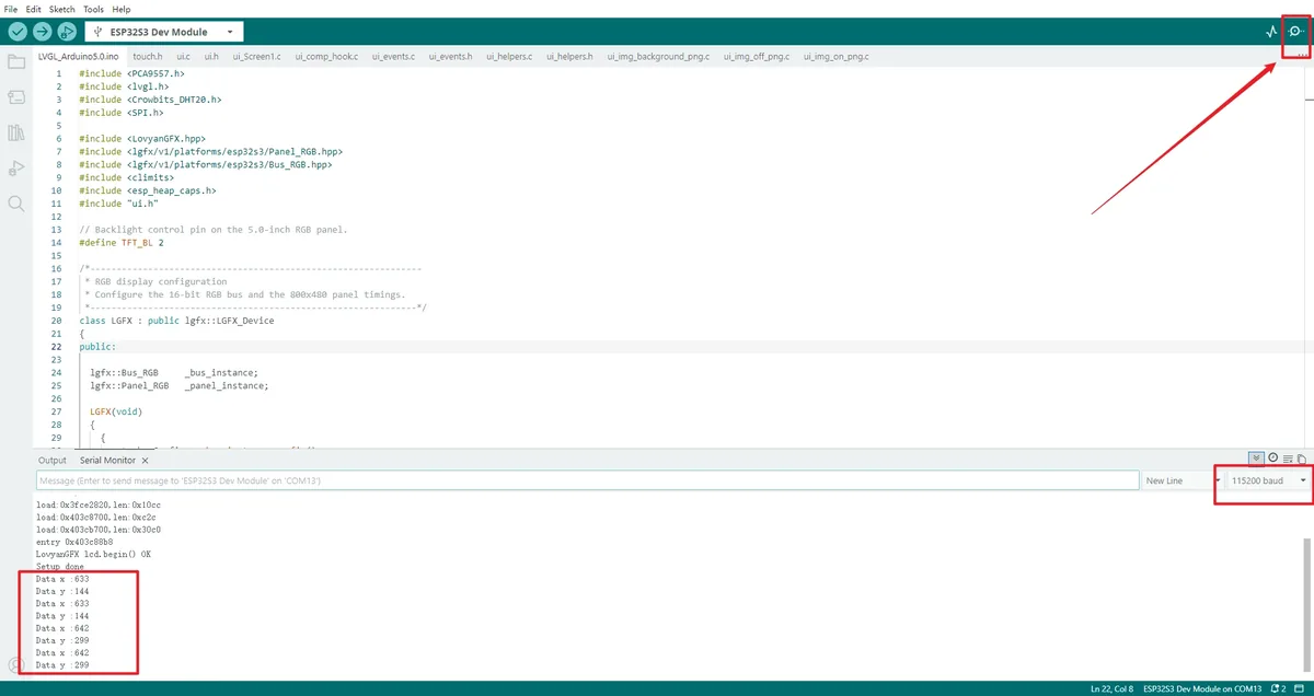
Click Serial Monitor in the top-right corner and set the baud rate to 115200. After reset, you should see LovyanGFX lcd.begin() OK and Setup done; when the screen is touched, Data x and Data y should also be output. 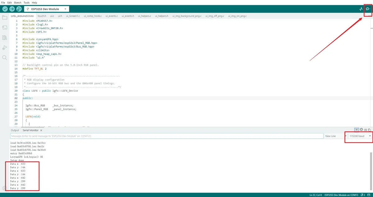
5. Hardware Operation Steps
With the power off, connect the DHT20 module to the board's IIC interface, and connect the LED module to the interface labeled GPIO_D.
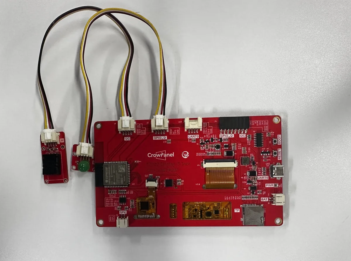
Reconnect a USB cable that supports data transfer. After upload completes and the board auto-resets, the screen backlight should turn on, and the interface should show temperature, humidity, and two buttons labeled ON and OFF.
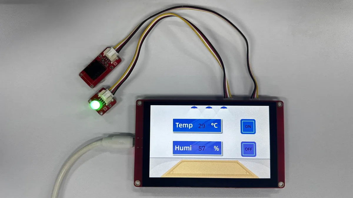
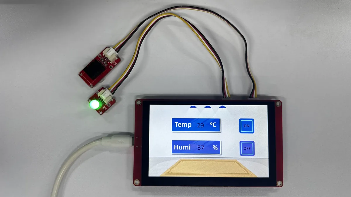
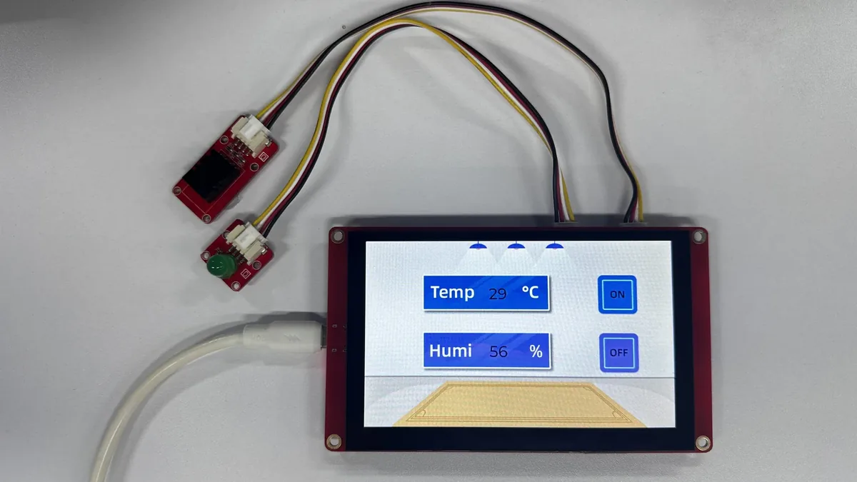
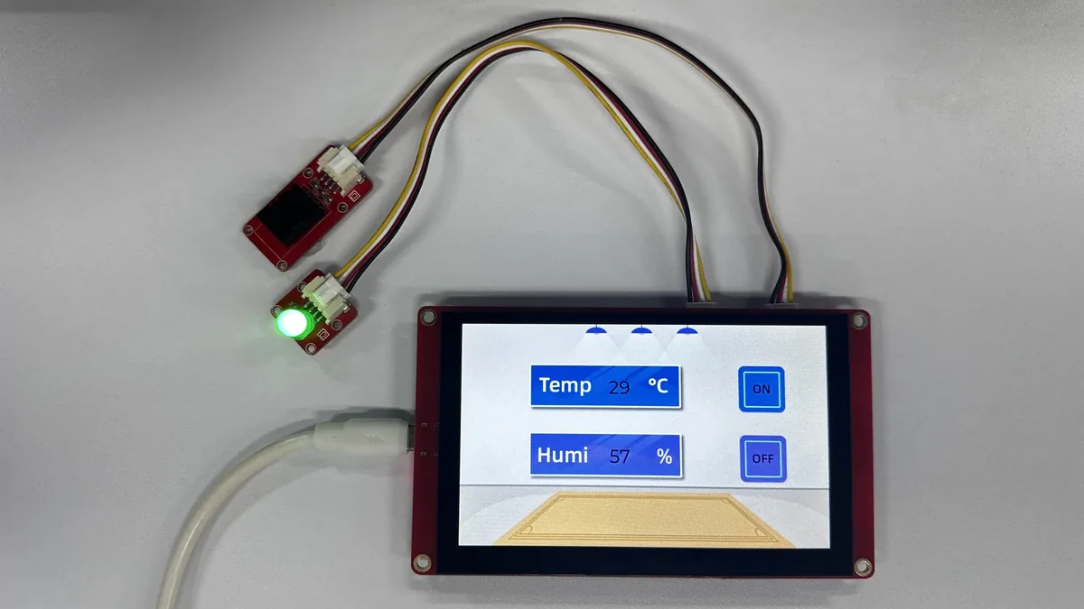
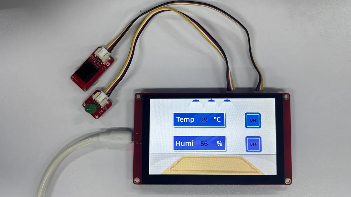
Tap ON and OFF in turn with your finger, and observe whether the LED lights up and goes out accordingly, while checking whether the serial monitor outputs the corresponding status. Do not press the screen with sharp or conductive objects.
ON -> LED lights up.
OFF -> LED goes out.
6. Key Code Explanation
6.1 RGB Panel and LVGL Frame Refresh
The LGFX constructor configures 16 RGB data lines, the DE/VSYNC/HSYNC/PCLK timing, and the 800×480 panel size. The four dimensions below must match the actual panel; a wrong value will cause misaligned, garbled, or incompletely refreshed images.
// LVGL uses these dimensions when it creates the display and frame buffers.
static constexpr uint32_t screenWidth = 800;
static constexpr uint32_t screenHeight = 480;

// Keep LVGL's drawing area aligned with the panel's physical resolution.
auto panelConfig = _panel_instance.config();
panelConfig.memory_width = 800;
panelConfig.memory_height = 480;
panelConfig.panel_width = 800;
panelConfig.panel_height = 480;
_panel_instance.config(panelConfig);
my_disp_flush() submits the complete frame buffer selected by LVGL to presentFrameBuffer(). The last line, lv_display_flush_ready(), is LVGL's completion notification; removing it will make LVGL keep waiting for the current frame, and the interface will stop refreshing.
void my_disp_flush(lv_display_t *display, const lv_area_t *area, uint8_t *pixelMap)
{
  // Switch the RGB controller to the complete frame selected by LVGL.
  if (!lcd._bus_instance.presentFrameBuffer(pixelMap)) {
    Serial.println("LovyanGFX VSYNC frame switch timeout");
  }
  // Always release LVGL's renderer after the panel has accepted the frame.
  lv_display_flush_ready(display);
}
// Reuse LovyanGFX's two full-screen RGB buffers for tear-free VSYNC swaps.
lv_color_t *frameBuffer0 = (lv_color_t *)lcd._bus_instance.getFrameBuffer(0);
lv_color_t *frameBuffer1 = (lv_color_t *)lcd._bus_instance.getFrameBuffer(1);
lv_display_t *display = lv_display_create(screenWidth, screenHeight);
lv_display_set_color_format(display, LV_COLOR_FORMAT_RGB565);
lv_display_set_flush_cb(display, my_disp_flush);
lv_display_set_buffers(display, frameBuffer0, frameBuffer1,
                       screenWidth * screenHeight * sizeof(lv_color_t),
                       LV_DISPLAY_RENDER_MODE_FULL);
LV_DISPLAY_RENDER_MODE_FULL means using the complete dual frame buffer of 800×480. It works together with the RGB panel's VSYNC switching; the cost is higher PSRAM usage, so OPI PSRAM must be selected in the Arduino IDE.
6.2 GT911 Input Callback
touch.h reads the GT911's first touch point over I2C and maps the raw coordinates to 0..799 and 0..479. my_touchpad_read() writes the press/release state and coordinates into LVGL's lv_indev_data_t, so button events do not need to read the hardware directly.
void my_touchpad_read(lv_indev_t *indev, lv_indev_data_t *data)
{
  // Only report a press when the touch driver has a fresh, valid sample.
  if (touch_has_signal())
  {
    if (touch_touched())
    {
      data->state = LV_INDEV_STATE_PR;
      // Forward the mapped panel coordinates to LVGL's pointer device.
      data->point.x = touch_last_x;
      data->point.y = touch_last_y;
      Serial.print("Data x :");
      Serial.println(touch_last_x);
      Serial.print("Data y :");
      Serial.println(touch_last_y);
    }
    else if (touch_released())
    {
      // Explicitly release the pointer so widgets do not remain pressed.
      data->state = LV_INDEV_STATE_REL;
    }
  }
  else
  {
    // A missing sample is treated as released rather than reusing stale data.
    data->state = LV_INDEV_STATE_REL;
  }
  delay(15);
}
// Register GT911 as LVGL's pointer source for the generated UI widgets.
lv_indev_t *indev = lv_indev_create();
lv_indev_set_type(indev, LV_INDEV_TYPE_POINTER);
lv_indev_set_read_cb(indev, my_touchpad_read);
LV_INDEV_TYPE_POINTER lets LVGL treat the GT911 as a finger pointer device. If lv_indev_set_read_cb() is omitted, the interface will still display, but none of the buttons will respond to touch.
6.3 DHT20 and UI Labels
The main loop reads the DHT20 once per second and updates only ui_TempLabel and ui_HumiLabel. The sensor read is not placed in a blocking loop during initialization, so LVGL's lv_timer_handler() still executes each round, ensuring continuous touch feedback.
static uint32_t lastSensorRead = 0;
static int lastTemperature = INT_MIN;
static int lastHumidity = INT_MIN;
uint32_t now = millis();

// Limit sensor traffic to one measurement per second without blocking LVGL.
if (now - lastSensorRead >= 1000) {
  lastSensorRead = now;
  int temperature = (int)dht20.getTemperature();
  int humidity = (int)dht20.getHumidity();
  char DHT_buffer[6];

  // Update each label only when its displayed value has changed.
  if (temperature != lastTemperature) {
    lastTemperature = temperature;
    snprintf(DHT_buffer, sizeof(DHT_buffer), "%d", temperature);
    lv_label_set_text(ui_TempLabel, DHT_buffer);
  }
  if (humidity != lastHumidity) {
    lastHumidity = humidity;
    snprintf(DHT_buffer, sizeof(DHT_buffer), "%d", humidity);
    lv_label_set_text(ui_HumiLabel, DHT_buffer);
  }
}
lastTemperature and lastHumidity avoid repeatedly refreshing the labels when the value has not changed. If the object names in the UI do not match ui_TempLabel and ui_HumiLabel, the project will report an undeclared object at compile time, or the modified UI will fail to display live data.
6.4 LED Event Chain
The ui.c generated by SquareLine Studio calls TurnOn() and TurnOff() on the button's release event; ui_events.c then sets the global led to 1 or 0, and the main loop finally writes the state to GPIO38. This layering lets the UI callback only express a "request", while the hardware output is concentrated in the application loop.
/** Route the On button's release event to the application LED request. */
void ui_event_OnButton(lv_event_t * e)
{
    lv_event_code_t event_code = lv_event_get_code(e);
    if(event_code == LV_EVENT_RELEASED) {
        TurnOn(e);
    }
}

/** Route the Off button's release event to the application LED request. */
void ui_event_OffButton(lv_event_t * e)
{
    lv_event_code_t event_code = lv_event_get_code(e);
    if(event_code == LV_EVENT_RELEASED) {
        TurnOff(e);
    }
}
extern int led;

/**
 * @brief Request the application to turn the LED on.
 * @param e LVGL event context (unused by this callback).
 */
void TurnOn(lv_event_t * e)
{
    led = 1;
}

/**
 * @brief Request the application to turn the LED off.
 * @param e LVGL event context (unused by this callback).
 */
void TurnOff(lv_event_t * e)
{
    led = 0;
}
// Apply the state requested by the generated UI callbacks to GPIO 38.
if(led == 1)
  digitalWrite(38, HIGH);
if(led == 0)
  digitalWrite(38, LOW);

lv_timer_handler();
delay(10);
If the event condition is changed from LV_EVENT_RELEASED to LV_EVENT_PRESSED, the LED will change immediately when the finger presses down; keeping the current writing changes it after release, which makes accidental touches easier to avoid. Do not delete lv_timer_handler(), otherwise LVGL will not process button events or refresh labels.
7. UI Resource Creation and Integration
This section uses SquareLine Studio 1.6.1 to demonstrate the interface creation process again. The course already provides the exported UI files; beginners can first read this section to understand the workflow, then directly use the files in the project to complete compilation. When creating a new project, you must select LVGL 9.1.0;
How to download SquareLine Studio: https://www.elecrow.com/wiki/Create_LVGL_UI_with_SquareLine_Studio.html.
Open SquareLine Studio 1.6.1, click Create at the top to create a new project, select 9.1 for the LVGL major version, and choose Elecrow for the vendor category. From the template list, select DIS07050H - ESP32 5inch HMI Display 800x480 RGB - Arduino-IDE. This template is designed for the Elecrow CrowPanel 5-inch capacitive touchscreen and comes with preset parameters of 800×480 resolution and LVGL9.
Note: This template is an Arduino project template dedicated to the Elecrow CrowPanel. It directly generates LVGL UI code that matches the hardware. If you switch to a different display model, you must select the corresponding hardware template and verify the resolution and color depth settings.

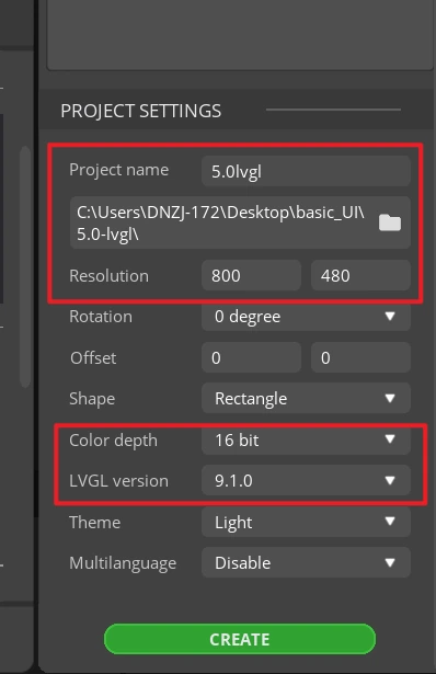
Enter the project name, set the LVGL version to 9.1.0, set the resolution to width 800 and height 480, set the color depth to 16 bit, then click CREATE. After creation, the canvas should be in landscape orientation at 800×480.
- Note: A
16 bitcolor depth can represent 65,536 colors using an RGB 5:6:5 pixel format. Keep this consistent with the project's color configuration.
After the project opens, select Screen1 in the Screens panel on the left, and confirm that the central canvas is blank and the Inspector on the right shows the Screen properties. All subsequent widgets will be added to this page.
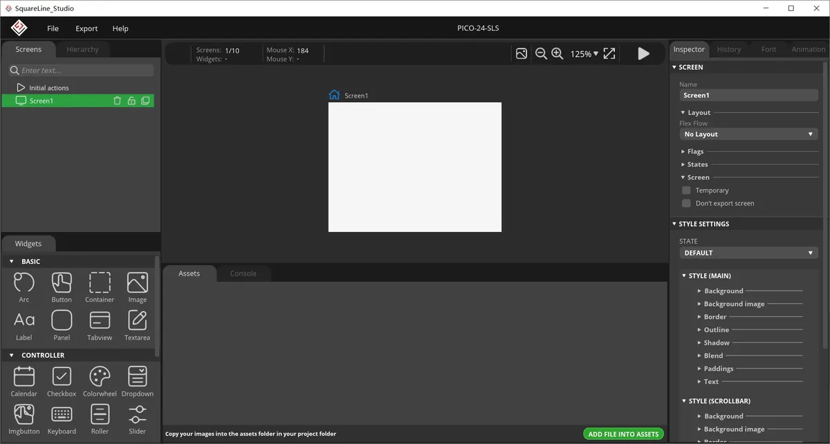
In the Assets area, click ADD FILE TO ASSETS and import background.png, on.png, and off.png in sequence. After importing, you should see three thumbnails.
Material link:
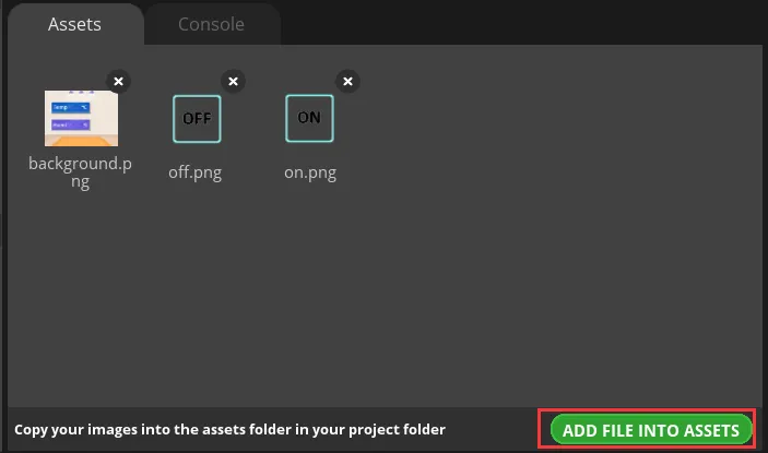
Note: Image assets support only the PNG format. The pixel dimensions of an image should be smaller than the project screen size. Keep each image under 100 KB, and ideally within 30 KB, to avoid affecting display smoothness.
Select Screen1, then on the right expand STYLE SETTINGS > STYLE (MAIN) > Background and enable the background image setting.
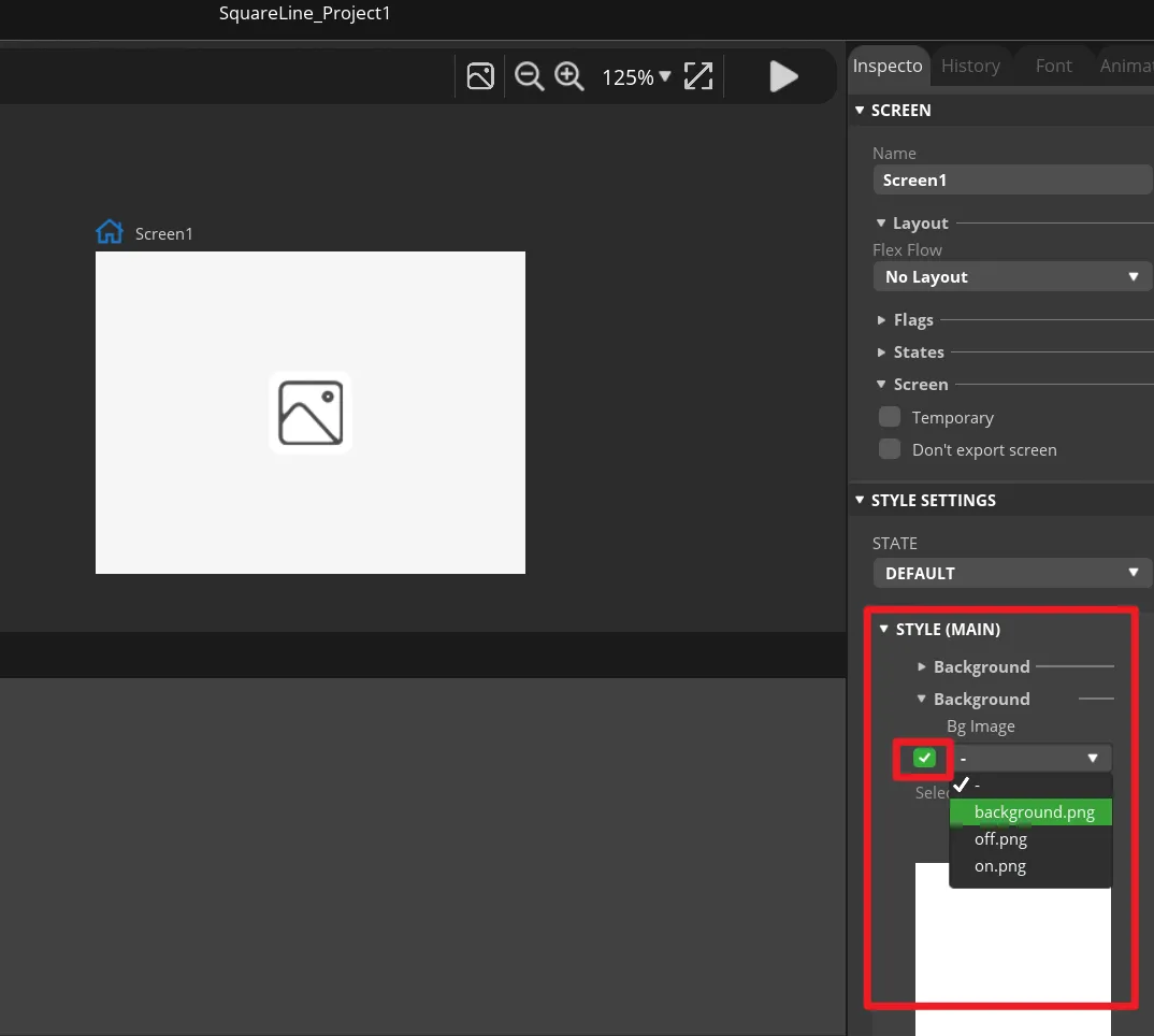
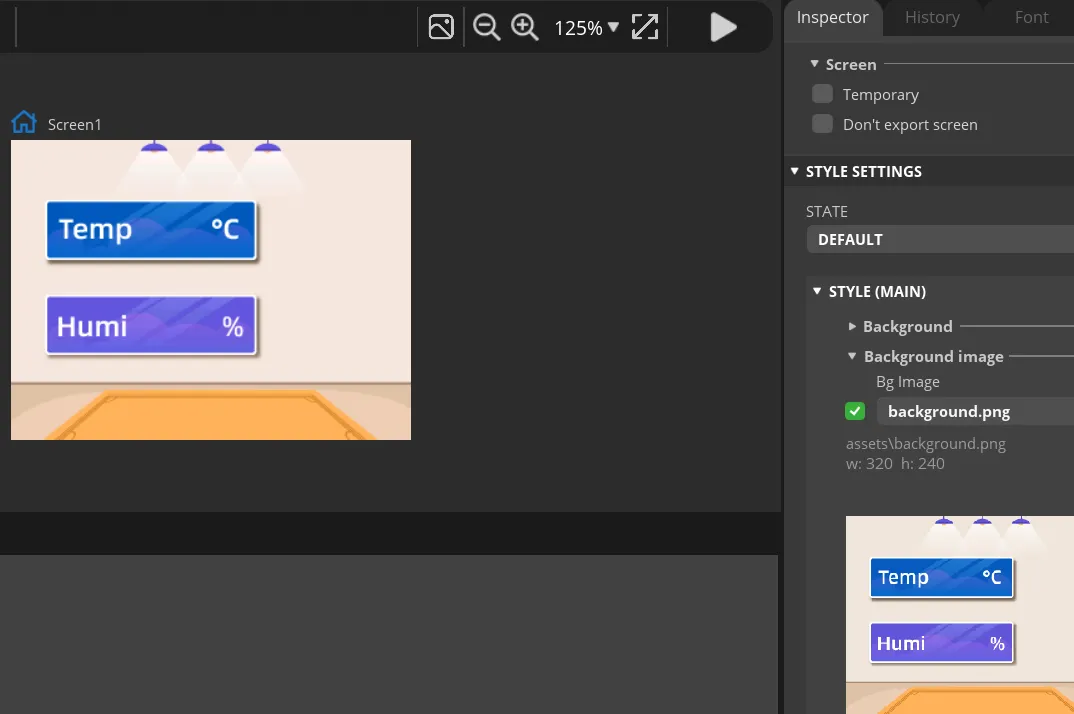
In Bg Image, select background. The course background image should appear on the canvas immediately, and it should fully cover the entire page.
In the Widgets panel on the left, click Label to add Label1 to Screen1. This label will be updated by the program with the temperature value.
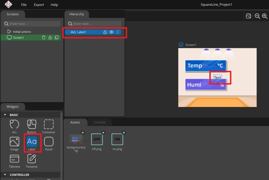
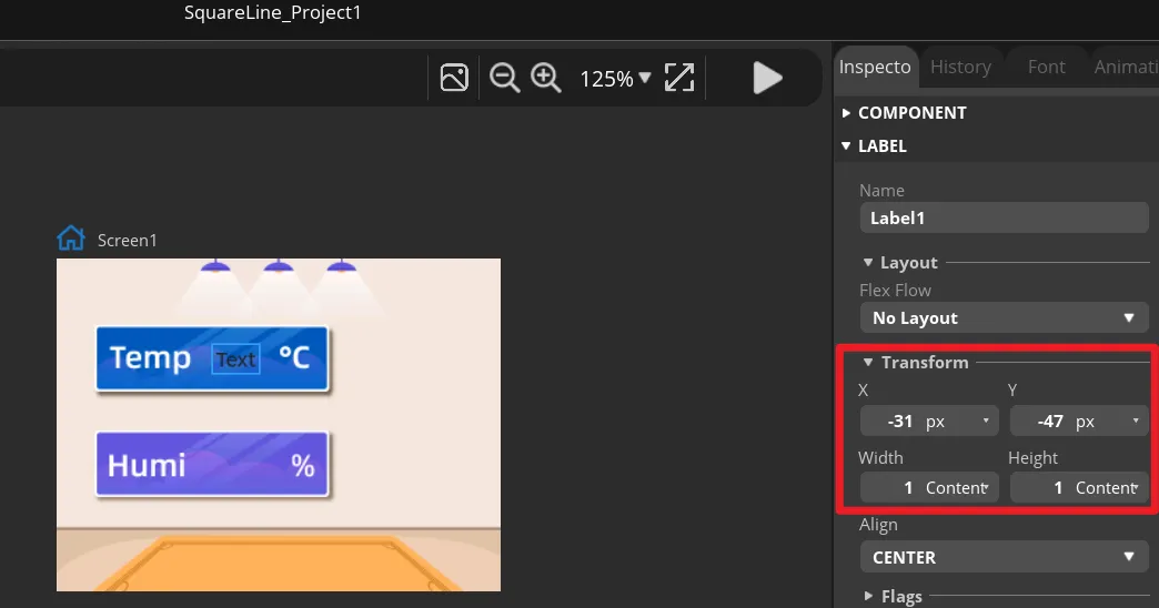
Select Label1, and in Transform adjust the X and Y position and the width and height so that it sits within the temperature display area of the background image. You can also drag it first and then fine-tune with the numeric values.
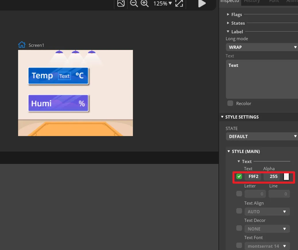
In Label1's STYLE (MAIN), change the text color to white and set an appropriate font size. The text on the canvas should be clearly visible and not extend beyond the background frame.
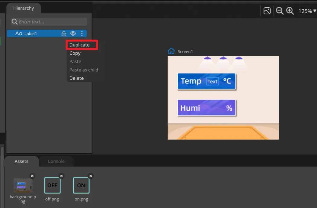
Right-click Label1 and choose Duplicate to create Label2, then move it to the humidity display area. Keep the names Label1 and Label2, because the main program updates them by name.
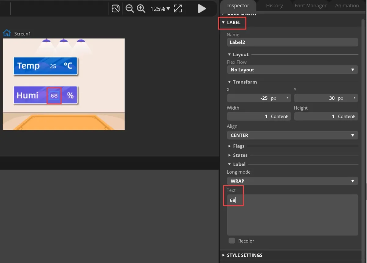
Select the two Labels one by one, and in Text enter default numbers that are convenient for preview. These are only design-time placeholder values; once the development board runs, they will be replaced by DHT20 readings.
In Widgets, click Button to add Button1, and drag it to the ON area on the right side of the interface.
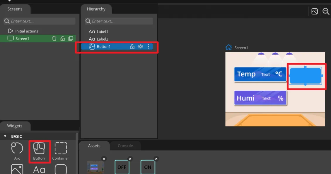
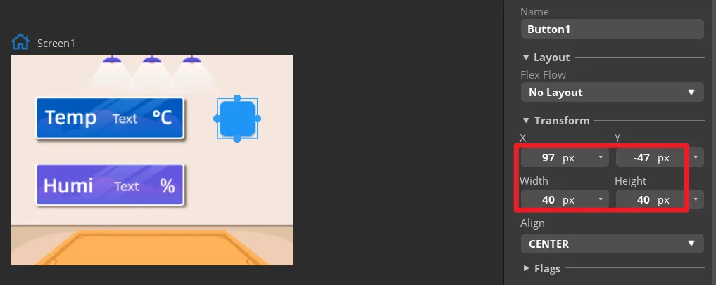
In Transform, set the size of Button1 and adjust its position so that the button aligns with the ON area in the background.
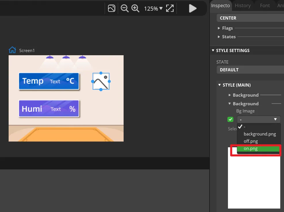
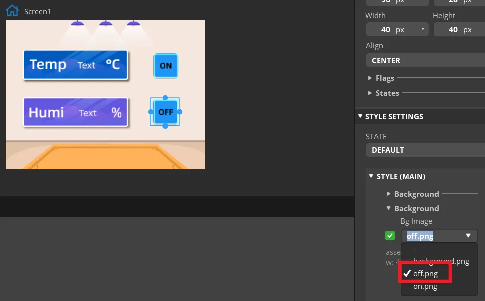
Expand Button1's STYLE (MAIN) > Background and select on.png as the background image. The ON icon should appear on the canvas.
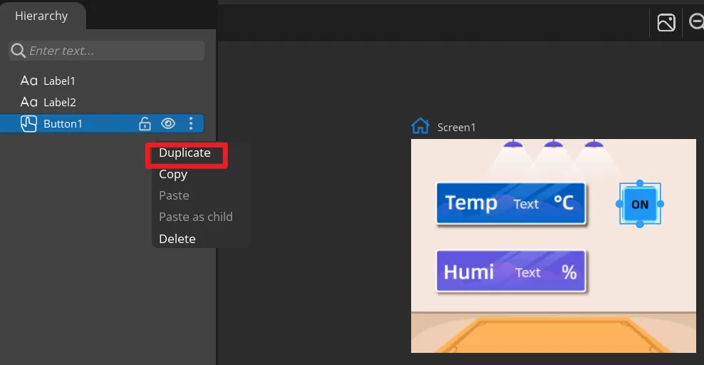
Duplicate Button1 to get Button2, move it to the OFF area, and change the background image to off.png. Keep the names Button1 and Button2 so they correspond to the exported event functions.
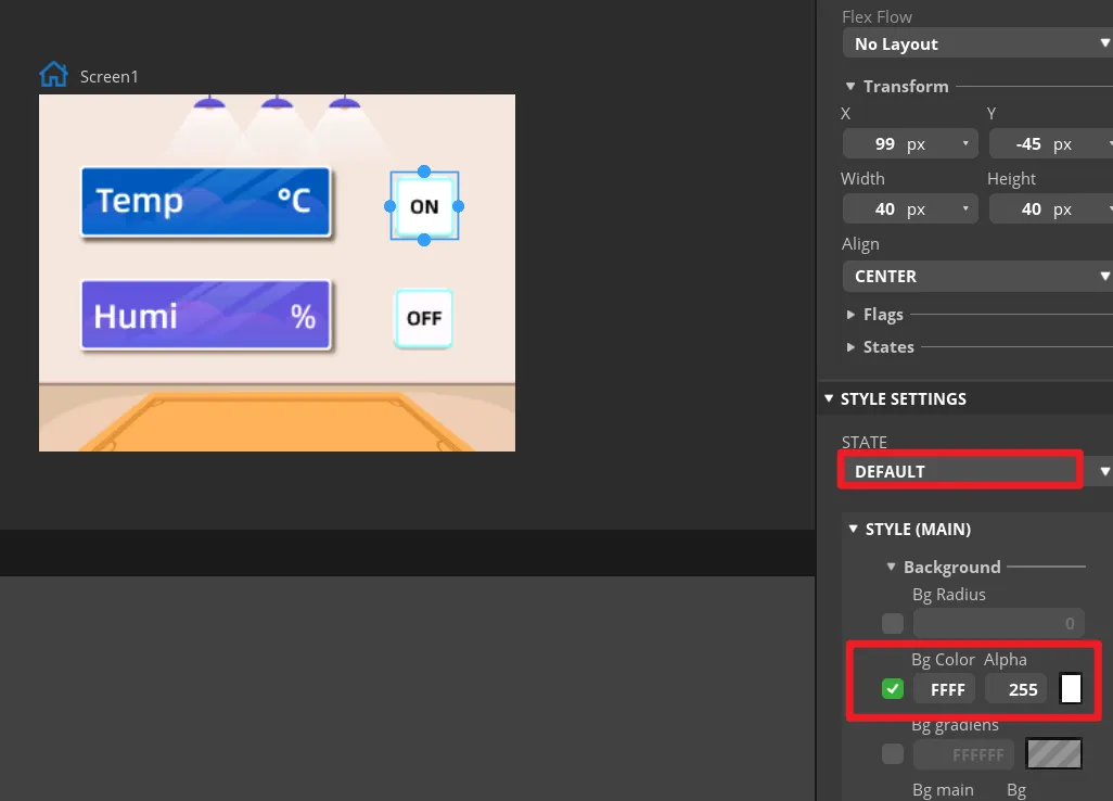
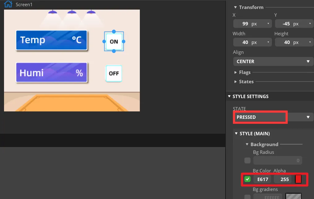
In the STATE settings of both buttons, check the DEFAULT and PRESSED states. The pressed state can use a distinct color change so that, during preview, you can tell whether a button is pressed. In "Inspector" -> "Style Settings" -> "State", set the displayed background color to white, and display red when in the "Fixed state". Apply the same parameters to the "OFF" button.
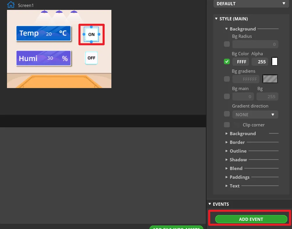
Select Button1 and click ADD EVENT.
Select "CLICKED" as the trigger condition, and in "Action" choose the trigger event. This will be modified later in the generated program to implement the LED control function.
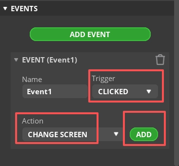
Note: Because the buttons ultimately control the LED on/off, you can add any event here first, so that the exported UI file generates the button event code framework. The LED control code will be modified in a later step.
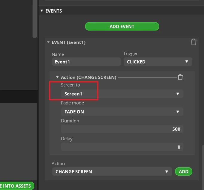
Complete this event. Here, I choose to switch screens, that is, switch to the Screen1 screen.
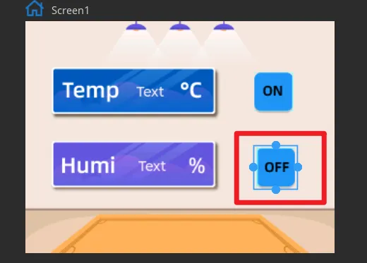
Add the event to Button2 in the same way (the state is "OFF").
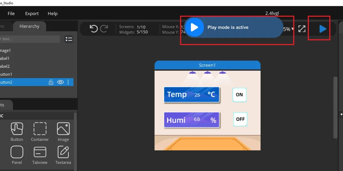
Click Run.
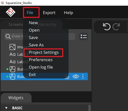
Open File > Project Settings, then configure the relevant settings for the exported files.
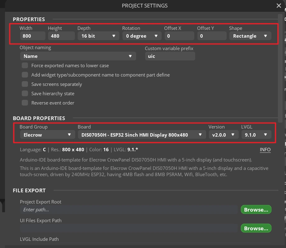
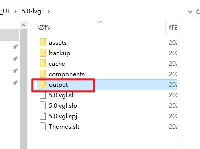
Set the export directory to an easy-to-find path consisting of English characters only, create a new output folder, confirm that the LVGL Include Path is lvgl.h, then click APPLY CHANGES.
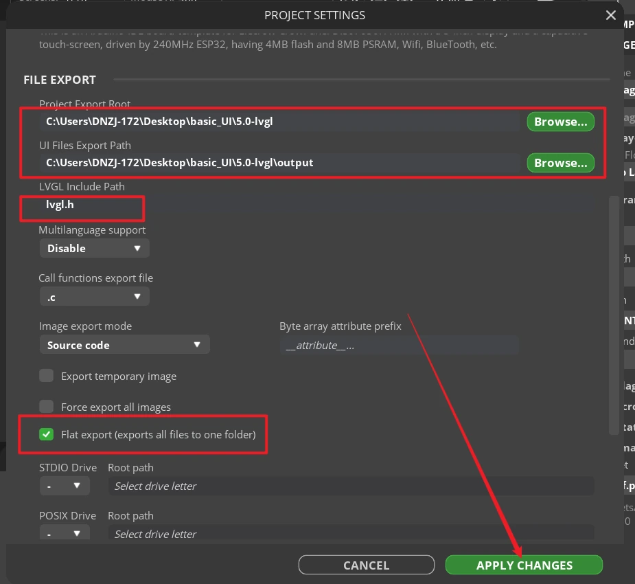
Tip: After selecting Flat export, all output files are placed in the same folder, and the program does not need to modify the file paths again. If Flat export is not selected, the files are scattered across different folders, which the compiler may fail to recognize automatically—usually requiring manual path changes—so it is recommended to keep it checked.
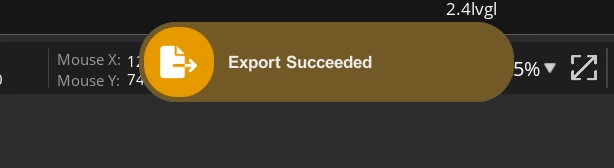
Click Export > Export UI Files. After the export completes, the target directory should contain ui.c, ui.h, ui_Screen1.c, the event file, helper files, and the image array file.
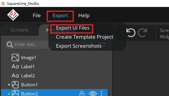
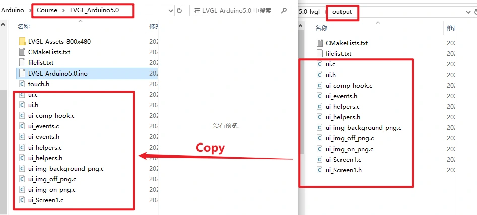
Close the Arduino IDE and copy all exported .c and .h files to the directory containing LVGL_Arduino5.0.ino.
Reopen the project, and in the two button event functions in ui_Screen1.c keep the event type check, and have the ON event execute led = 1; and the OFF event execute led = 0;. Then return to the main program and click Verify to confirm there are no errors about a missing led or UI object.
Then, replace the function calls in the Button1 and Button2 functions with the functions used to turn the LED on and off.
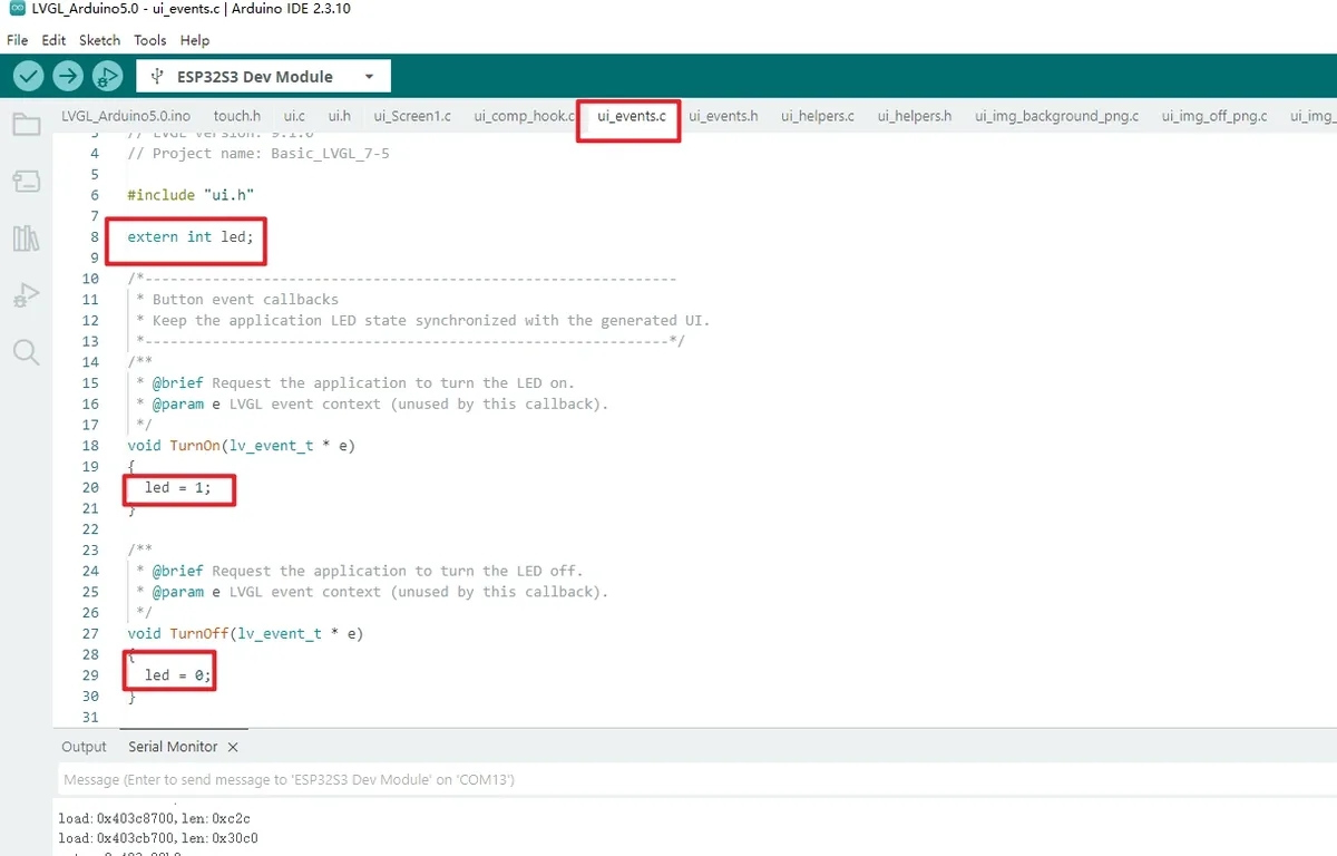
In the project, ui_Screen1.c ultimately creates two white numeric labels and two image buttons. If you change widget names or asset names in SquareLine Studio, you must synchronously check the ui.h declarations, the ui_Screen1.c references, and ui_Label1 and ui_Label2 in the main program.
8. Experimental Results
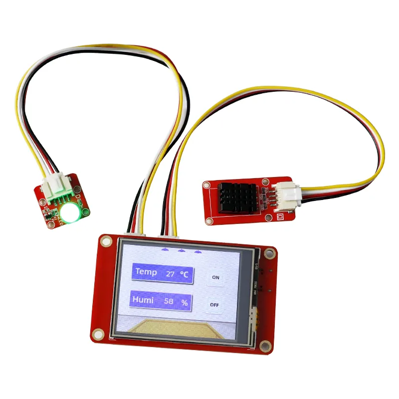
After power-on, the backlight turns on, and the screen displays the background image, the temperature/humidity values, and the ON/OFF buttons.
After clicking ON, the LED corresponding to GPIO38 lights up.
After clicking OFF, it turns off.
9. Code Download
Arduino project: Arduino_5.0.
Example Demo of ESP32 HMI Function
Example1: LED blinking.
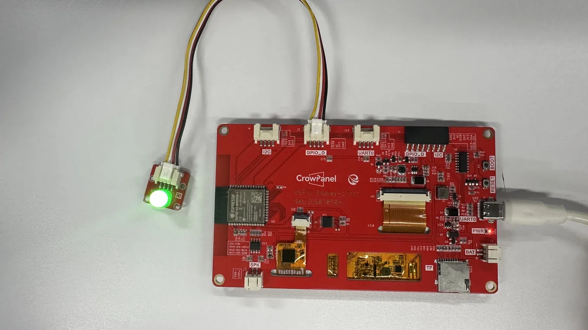
Connect the LED to the GPIO_D (IO38) port, then flash the following code into the chip. The LED will then start blinking.
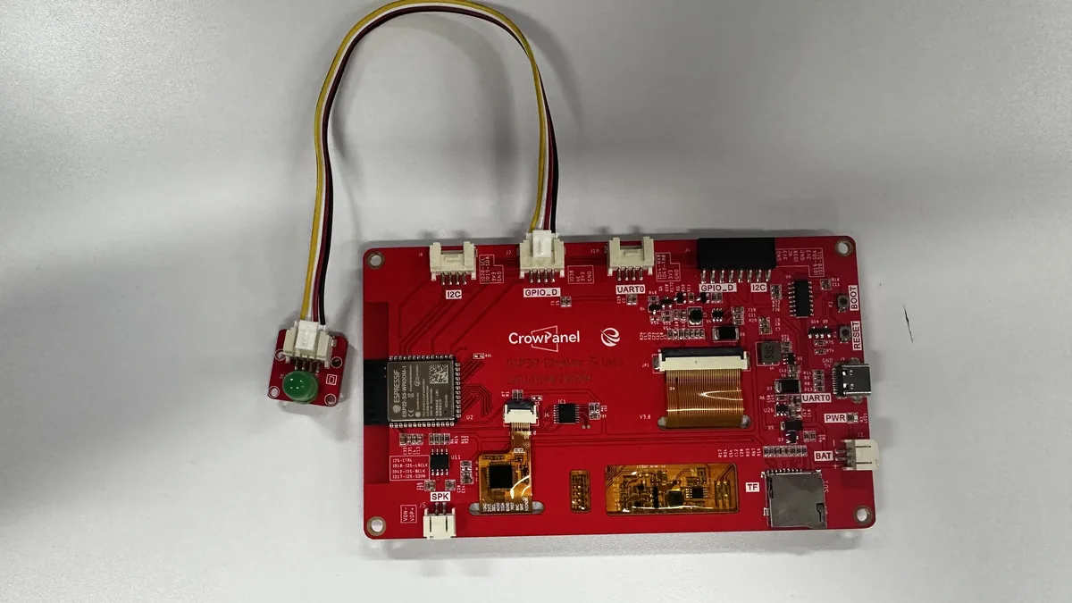
// GPIO 38 drives the on-board LED through the display carrier board.
#define D_PIN 38

/**
 * @brief Configure the serial port and LED output.
 *
 * Called once after reset before the repeating blink sequence starts.
 */
void setup() {
  Serial.begin(115200);
  pinMode(D_PIN, OUTPUT);
}

/**
 * @brief Alternate the LED state at a visible rate.
 *
 * Each state is held for 500 ms, so a complete on/off cycle lasts one
 * second. This makes the GPIO result easy to verify without instruments.
 */
void loop() {
  digitalWrite(D_PIN, HIGH);
  delay(500);
  digitalWrite(D_PIN, LOW);
  delay(500);
}
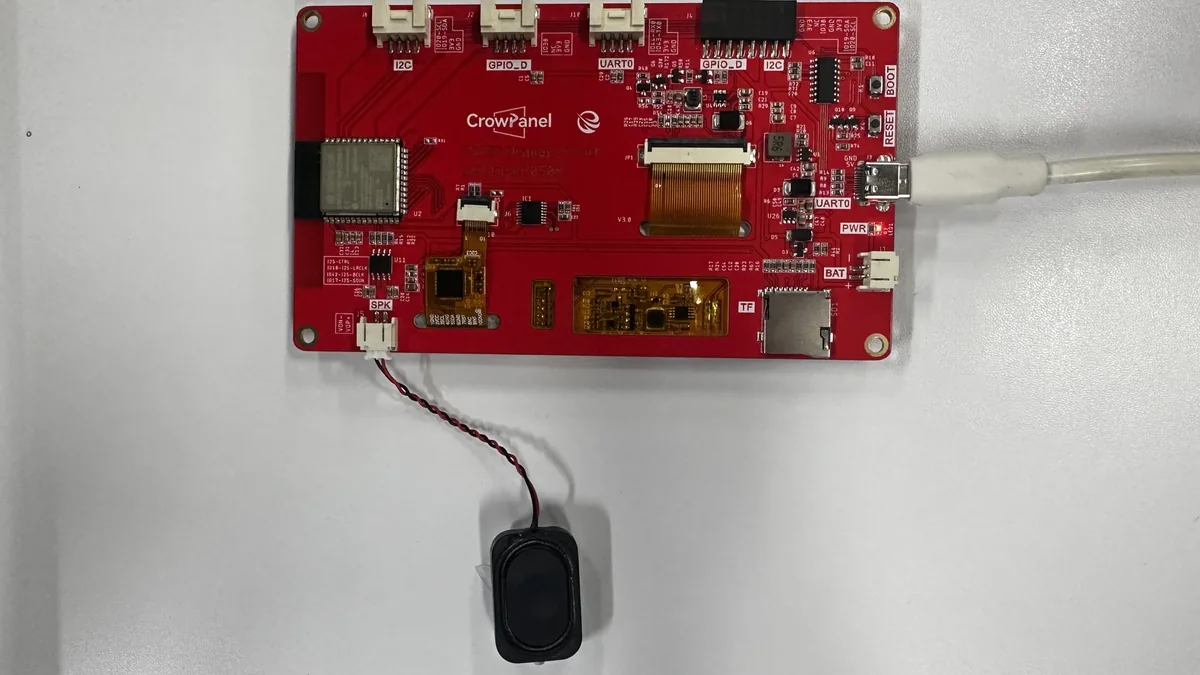
Example2: Play music
Connect the speaker to the SPK port. Check whether the ESP32-audioI2S library is already installed (copy the ESP32-audioI2S folder from the downloaded library files to the .../arduino/libraries directory). Upload the following code to the chip.
#include <driver/i2s.h>
#include <math.h>

#define I2S_DOUT  17
#define I2S_BCLK  42
#define I2S_LRC   18

// I2S audio format used by the external amplifier.
const int sampleRate = 44100;
const int16_t AMPLITUDE = 32767;

// Note frequencies in hertz used by the demonstration melody.
#define NOTE_C4  262
#define NOTE_D4  294
#define NOTE_E4  330
#define NOTE_F4  349
#define NOTE_G4  392
#define NOTE_A4  440
#define NOTE_B4  494
#define NOTE_C5  523
#define NOTE_D5  587
#define NOTE_E5  659
#define NOTE_F5  698
#define NOTE_G5  784

// Each entry contains one frequency and its duration in milliseconds.
struct Note {
  int freq;
  int durationMs;
};

Note melody[] = {
  // First phrase.
  {NOTE_G4, 200}, {NOTE_G4, 200}, {NOTE_A4, 400}, {NOTE_G4, 400}, {NOTE_C5, 400}, {NOTE_B4, 800},
  // Second phrase.
  {NOTE_G4, 200}, {NOTE_G4, 200}, {NOTE_A4, 400}, {NOTE_G4, 400}, {NOTE_D5, 400}, {NOTE_C5, 800},
  // Third phrase.
  {NOTE_G4, 200}, {NOTE_G4, 200}, {NOTE_G5, 400}, {NOTE_E5, 400}, {NOTE_C5, 400}, {NOTE_B4, 200}, {NOTE_A4, 600},
  // Fourth phrase.
  {NOTE_F5, 200}, {NOTE_F5, 200}, {NOTE_E5, 400}, {NOTE_C5, 400}, {NOTE_D5, 400}, {NOTE_C5, 800},
  // Zero duration marks the end of the melody table.
  {0, 0}
};

/**
 * @brief Configure I2S output and play the first melody pass.
 *
 * Called once after reset. The pin map and sample format must match the
 * amplifier connected to the 5.0-inch HMI board.
 */
void setup() {
  Serial.begin(115200);
  Serial.println("Happy Birthday I2S Test - Full Volume");

  i2s_config_t i2s_config = {
    .mode = (i2s_mode_t)(I2S_MODE_MASTER | I2S_MODE_TX),
    .sample_rate = sampleRate,
    .bits_per_sample = I2S_BITS_PER_SAMPLE_16BIT,
    .channel_format = I2S_CHANNEL_FMT_RIGHT_LEFT,
    .communication_format = I2S_COMM_FORMAT_STAND_I2S,
    .intr_alloc_flags = ESP_INTR_FLAG_LEVEL1,
    .dma_buf_count = 8,
    .dma_buf_len = 64,
    .use_apll = false,
    .tx_desc_auto_clear = true,
    .fixed_mclk = 0
  };

  i2s_pin_config_t pin_config = {
    .bck_io_num = I2S_BCLK,
    .ws_io_num = I2S_LRC,
    .data_out_num = I2S_DOUT,
    .data_in_num = I2S_PIN_NO_CHANGE
  };

  i2s_driver_install(I2S_NUM_0, &i2s_config, 0, NULL);
  i2s_set_pin(I2S_NUM_0, &pin_config);
  i2s_set_clk(I2S_NUM_0, sampleRate, I2S_BITS_PER_SAMPLE_16BIT, I2S_CHANNEL_STEREO);

  playMelody();
}

/**
 * @brief Generate a sine wave (or silence) and send it to both I2S channels.
 *
 * @param freq Tone frequency in hertz; zero requests a rest.
 * @param durationMs Tone or rest duration in milliseconds.
 * @return None.
 * @note Called by playMelody() for each table entry.
 */
void playTone(int freq, int durationMs) {
  if (freq == 0) {
    // A rest is sent as zero-valued stereo samples.
    int samplesCount = sampleRate * durationMs / 1000;
    int16_t silence[128] = {0};
    size_t bytes_written;

    for (int i = 0; i < samplesCount; i += 64) {
      int batch = min(64, samplesCount - i);
      i2s_write(I2S_NUM_0, silence, batch * sizeof(int16_t) * 2, &bytes_written, portMAX_DELAY);
    }
    return;
  }

  // Generate the requested tone in small DMA-sized batches.
  int samplesCount = sampleRate * durationMs / 1000;
  float phase = 0;
  float phaseIncrement = 2.0 * PI * freq / sampleRate;

  size_t bytes_written;

  for (int i = 0; i < samplesCount; i += 64) {
    int16_t samples[128];
    int batch = min(64, samplesCount - i);

    for (int j = 0; j < batch; j++) {
      int16_t sample = (int16_t)(sin(phase) * AMPLITUDE);
      samples[j * 2]     = sample;
      samples[j * 2 + 1] = sample;
      phase += phaseIncrement;
      if (phase > 2.0 * PI) phase -= 2.0 * PI;
    }

    i2s_write(I2S_NUM_0, samples, batch * sizeof(int16_t) * 2, &bytes_written, portMAX_DELAY);
  }
}

/**
 * @brief Play every note until the zero-duration end marker is reached.
 *
 * @return None.
 * @note Called at startup and once per loop iteration.
 */
void playMelody() {
  int i = 0;
  while (melody[i].durationMs > 0) {
    playTone(melody[i].freq, melody[i].durationMs);
    playTone(0, 50);
    i++;
  }
}

/**
 * @brief Wait between complete melody passes and replay the melody.
 */
void loop() {
  delay(2000);
  playMelody();
}
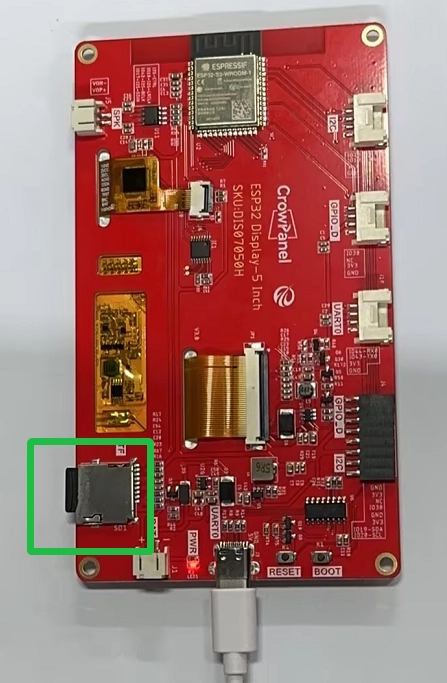
Example 3: Initialize the SD Card Slot
Insert an SD card formatted as FAT16 or FAT32. Cards using other file systems may not be recognized.
#include <Wire.h>
#include <SPI.h>
#include <SD.h>
#include <FS.h>

// SD wiring for the 5.0-inch HMI card slot.
#define SD_MOSI 11
#define SD_MISO 13
#define SD_SCK 12
#define SD_CS 10
/**
 * @brief Initialize the serial port, SPI bus, and SD card.
 *
 * Called once after reset. The directory tree is printed when mounting
 * succeeds, making the card status visible in the serial monitor.
 */
void setup() {
  Serial.begin( 115200 );
  SPI.begin(SD_SCK, SD_MISO, SD_MOSI);
  delay(100);
  if (SD_init() == 1)
  {
    Serial.println("Card Mount Failed");
  }
  else
    Serial.println("initialize SD Card successfully");
}

void loop() {
}

/**
 * @brief Mount the SD card and list its top-level files and directories.
 *
 * @return 0 when the card is ready; 1 when mounting or card detection fails.
 * @note Called by setup() after the SPI pins have been configured.
 */
int SD_init()
{

  if (!SD.begin(SD_CS))
  {
    Serial.println("Card Mount Failed");
    return 1;
  }
  uint8_t cardType = SD.cardType();

  if (cardType == CARD_NONE)
  {
    Serial.println("No TF card attached");
    return 1;
  }

  uint64_t cardSize = SD.cardSize() / (1024 * 1024);
  Serial.printf("TF Card Size: %lluMB\n", cardSize);
  listDir(SD, "/", 2);


  return 0;
}

/**
 * @brief Recursively print directory entries to the serial monitor.
 *
 * @param fs Filesystem instance to inspect.
 * @param dirname Directory path to open.
 * @param levels Maximum recursion depth.
 * @return None.
 * @note Called by SD_init() after a successful mount.
 */
void listDir(fs::FS & fs, const char *dirname, uint8_t levels)
{
  File root = fs.open(dirname);
  if (!root)
  {
    return;
  }
  if (!root.isDirectory())
  {
    Serial.println("Not a directory");
    return;
  }

  File file = root.openNextFile();
  while (file)
  {
    if (file.isDirectory())
    {
      Serial.print("  DIR : ");
      Serial.println(file.name());
      if (levels)
      {
        listDir(fs, file.name(), levels - 1);
      }
    }
    else
    {
      Serial.print("FILE: ");
      Serial.print(file.name());
      Serial.print("SIZE: ");
      Serial.println(file.size());
    }

    file = root.openNextFile();
  }
}
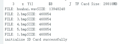
What to expect: The serial monitor displays the SD card capacity, followed by the file names and file sizes on the card, one by one.
Example 4: Initialize the Touch Panel
Upload the following code to the board, then open the serial monitor to view the touch information.
Use the library files and the corresponding touch.h file provided by us.
#include "touch.h"

/**
 * @brief Start the serial monitor and initialize the GT911 touch controller.
 *
 * Called once after reset. The touch driver performs the I2C setup and
 * controller reset; later polling is handled by loop().
 */
void setup() {
  Serial.begin(115200);
  touch_init();
}

/**
 * @brief Print each detected touch point to the serial monitor.
 *
 * The coordinates are already mapped to the 800x480 display by touch.h.
 */
void loop() {
  if (touch_has_signal())
  {
    if (touch_touched())
    {
      Serial.print("Data x :");
      Serial.println(touch_last_x);
      Serial.print("Data y :");
      Serial.println(touch_last_y);
    }
  }
}
Example 5: BLE
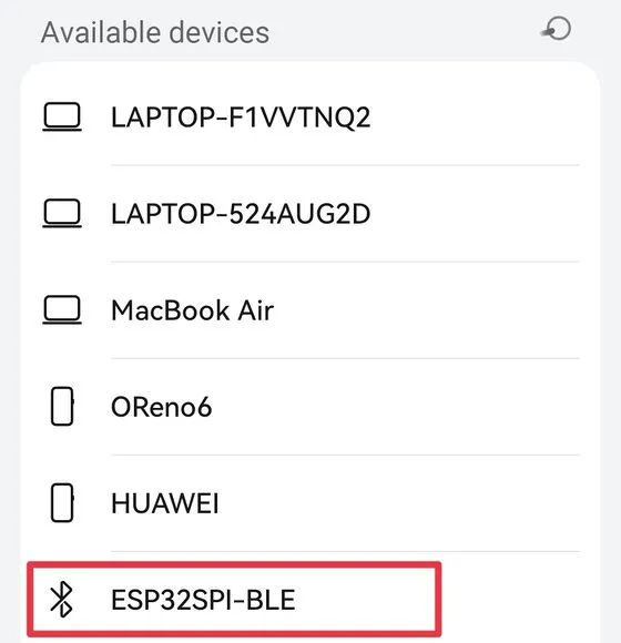
Upload the following code to the board, then use a phone to search for Bluetooth devices.
#include "BLEDevice.h"
#include "BLEServer.h"
#include "BLEUtils.h"
#include "BLE2902.h"
#include <BLECharacteristic.h>

// These handles keep the BLE server objects alive for the lifetime of the sketch.
BLEAdvertising* pAdvertising = NULL;
BLEServer* pServer = NULL;
BLEService *pService = NULL;
BLECharacteristic* pCharacteristic = NULL;
#define bleServerName "ESP32SPI-BLE"
#define SERVICE_UUID "6479571c-2e6d-4b34-abe9-c35116712345"
#define CHARACTERISTIC_UUID "826f072d-f87c-4ae6-a416-6ffdcaa02d73"

// Tracks whether a central device is currently connected to this server.
bool connected_state = false;

/**
 * @brief Update the connection flag when a BLE central connects or disconnects.
 */
class MyServerCallbacks: public BLEServerCallbacks
{
    void onConnect(BLEServer *pServer)
    {
      connected_state = true;
    }
    void onDisconnect(BLEServer *pServer)
    {
      connected_state = false;
    }

};
/**
 * @brief Create the BLE server, service, characteristic, and advertisement.
 *
 * Called once after reset. A phone or computer can discover the advertised
 * service and read/write the characteristic value "ELECROW".
 */
void setup() {
  Serial.begin(115200);
  BLEDevice::init(bleServerName);
  pServer = BLEDevice::createServer();
  pServer->setCallbacks(new MyServerCallbacks());
  pService = pServer->createService(SERVICE_UUID);

  pCharacteristic = pService->createCharacteristic(
                      CHARACTERISTIC_UUID,
                      BLECharacteristic::PROPERTY_READ | BLECharacteristic::PROPERTY_WRITE | BLECharacteristic::PROPERTY_NOTIFY);
  pCharacteristic->setValue("ELECROW");
  pAdvertising = BLEDevice::getAdvertising();
  pAdvertising->addServiceUUID(SERVICE_UUID);
  pAdvertising->start();
  pService->start();
}

/**
 * @brief Keep the BLE server alive.
 *
 * BLE callbacks handle connection events, so no polling work is required here.
 */
void loop() {

}
Example 6: Initialize Wi-Fi
Upload the following code to the ESP display. Note: replace the Wi-Fi network name and password with your actual values.
#include <WiFi.h>

// Replace these values with the network credentials used for the experiment.
const char *ssid = "elecrow888";
const char *password = "elecrow2014";

/**
 * @brief Connect to the configured Wi-Fi network and print the assigned IP.
 *
 * The function blocks until the station receives a connection, which makes
 * the successful connection condition unambiguous in the serial monitor.
 */
void setup() {
  Serial.begin(115200);
  WiFi.begin(ssid, password);
  WiFi.setAutoReconnect(true);
  while (WiFi.status() != WL_CONNECTED) {
    delay(100);
    Serial.println("connecting");
  }
  Serial.println("WiFi is connected.");
  Serial.println("IP address: ");
  Serial.println(WiFi.localIP());
}

/**
 * @brief Leave the Wi-Fi connection active.
 *
 * Reconnection is provided by the WiFi library, so the sketch has no
 * periodic polling task.
 */
void loop() {

}
Example 7: Connect the Crowtail-GPS Module via UART to Obtain Location
Because the USB-to-serial interface shares the same pins as the UART interface, the USB function and the UART function cannot be used at the same time. When flashing or uploading firmware, make sure to disconnect the UART interface.
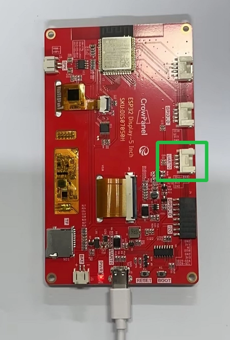
After the program has been uploaded successfully, connect the GPS module to the board and power the board back on through the USB interface.
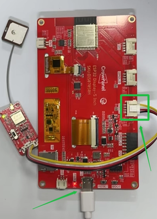
Note: For best results, choose a location with good weather and an open outdoor environment. This allows the GPS module to properly receive satellite signals, collect data, and display it on the screen.
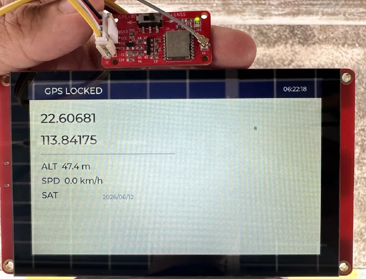
GPS module purchase link: https://www.elecrow.com/crowtailgps-p-1515.html.
#include <PCA9557.h>
#include <lvgl.h>
#include <SPI.h>
#include <LovyanGFX.hpp>
#include <lgfx/v1/platforms/esp32s3/Panel_RGB.hpp>
#include <lgfx/v1/platforms/esp32s3/Bus_RGB.hpp>

#define TFT_BL 2

// UART pins used by the external GPS receiver.
#define GPS_RX 44
#define GPS_TX 43
HardwareSerial gpsSerial(1);

// NMEA line buffer and the latest decoded navigation values.
char nmeaLine[128];
byte nmeaIndex = 0;

struct {
  bool valid = false;
  float lat = 0;
  float lon = 0;
  char latDir = 'N';
  char lonDir = 'E';
  float alt = 0;
  float speed = 0;
  uint8_t sats = 0;
  uint8_t fixType = 0;
  char timeStr[10] = "--:--:--";
  char dateStr[12] = "----/--/--";
} gps;

class LGFX : public lgfx::LGFX_Device
{
public:

  lgfx::Bus_RGB     _bus_instance;
  lgfx::Panel_RGB   _panel_instance;

  LGFX(void)
  {
    {
      auto busConfig = _bus_instance.config();
      busConfig.panel = &_panel_instance;
      const int8_t dataPins[16] = {8, 3, 46, 9, 1, 5, 6, 7, 15, 16, 4, 45, 48, 47, 21, 14};
      memcpy(busConfig.pin_data, dataPins, sizeof(dataPins));
      busConfig.pin_henable = 40;
      busConfig.pin_vsync = 41;
      busConfig.pin_hsync = 39;
      busConfig.pin_pclk = 0;
      busConfig.freq_write = 12000000;
      busConfig.hsync_polarity = 0;
      busConfig.hsync_front_porch = 8;
      busConfig.hsync_pulse_width = 4;
      busConfig.hsync_back_porch = 43;
      busConfig.vsync_polarity = 0;
      busConfig.vsync_front_porch = 8;
      busConfig.vsync_pulse_width = 4;
      busConfig.vsync_back_porch = 12;
      busConfig.pclk_active_neg = 1;
      busConfig.de_idle_high = 0;
      busConfig.pclk_idle_high = 0;
      _bus_instance.config(busConfig);
    }
    {
      auto panelConfig = _panel_instance.config();
      panelConfig.memory_width = 800;
      panelConfig.memory_height = 480;
      panelConfig.panel_width = 800;
      panelConfig.panel_height = 480;
      _panel_instance.config(panelConfig);
    }
    _panel_instance.setBus(&_bus_instance);
    setPanel(&_panel_instance);

  }
};

LGFX lcd;
static constexpr uint32_t screenWidth = 800;
static constexpr uint32_t screenHeight = 480;

/*******************************************************************************
   Please config the touch panel in touch.h
 ******************************************************************************/
#include "touch.h"

/* Display flushing */
void my_disp_flush(lv_display_t *display, const lv_area_t *area, uint8_t *pixelMap)
{
  if (!lcd._bus_instance.presentFrameBuffer(pixelMap)) {
    Serial.println("LovyanGFX VSYNC frame switch timeout");
  }
  lv_display_flush_ready(display);
}

void my_touchpad_read(lv_indev_t *indev, lv_indev_data_t *data)
{
  if (touch_has_signal())
  {
    if (touch_touched())
    {
      data->state = LV_INDEV_STATE_PR;

      /*Set the coordinates*/
      data->point.x = touch_last_x;
      data->point.y = touch_last_y;
      Serial.print( "Data x :" );
      Serial.
println( touch_last_x );

      Serial.
print( "Data y :" );
      Serial.println( touch_last_y );
    }
    else if (touch_released())
    {
      data->state = LV_INDEV_STATE_REL;
    }
  }
  else
  {
    data->state = LV_INDEV_STATE_REL;
  }
  delay(15);
}

// ==================== GPS Parsing Functions ====================
/** Validate the XOR checksum appended to an NMEA sentence. */
bool checkNMEA(const char* line) {
  const char* star = strchr(line, '*');
  if (!star || strlen(star) < 3) return false;
  byte calc = 0;
  for (const char* p = line + 1; *p && *p != '*'; p++) {
    calc ^= *p;
  }
  byte recv = (byte)strtol(star + 1, NULL, 16);
  return calc == recv;
}

/** Convert NMEA degrees/minutes text to signed decimal degrees. */
float dmToDd(const char* dm, char dir) {
  if (!dm || strlen(dm) < 3) return 0;
  float val = atof(dm);
  int deg = (int)(val / 100);
  float min = val - deg * 100;
  float dd = deg + min / 60.0;
  return (dir == 'S' || dir == 'W') ? -dd : dd;
}

/** Decode a GGA fix sentence into time, position, altitude, and satellites. */
void parseGGA(char* p) {
  char* tok = strtok(p, ",");
  tok = strtok(NULL, ","); // time
  if (tok && strlen(tok) >= 6) {
    snprintf(gps.timeStr, sizeof(gps.timeStr), "%c%c:%c%c:%c%c",
             tok[0], tok[1], tok[2], tok[3], tok[4], tok[5]);
  }
  tok = strtok(NULL, ","); // lat
  char* lat = tok;
  tok = strtok(NULL, ","); // N/S
  char latD = tok ? tok[0] : 'N';
  tok = strtok(NULL, ","); // lon
  char* lon = tok;
  tok = strtok(NULL, ","); // E/W
  char lonD = tok ? tok[0] : 'E';
  tok = strtok(NULL, ","); // fix
  gps.fixType = tok ? atoi(tok) : 0;
  gps.valid = (gps.fixType > 0);
  tok = strtok(NULL, ","); // sats
  gps.sats = tok ? atoi(tok) : 0;
  tok = strtok(NULL, ","); // hdop
  tok = strtok(NULL, ","); // alt
  gps.alt = (tok && strlen(tok) > 0) ? atof(tok) : 0;

  if (gps.valid) {
    gps.lat = dmToDd(lat, latD);
    gps.lon = dmToDd(lon, lonD);
    gps.latDir = latD;
    gps.lonDir = lonD;
  }
}

/** Decode an RMC sentence into position, speed, date, and validity. */
void parseRMC(char* p) {
  char* tok = strtok(p, ",");
  tok = strtok(NULL, ","); // time
  tok = strtok(NULL, ","); // status
  gps.valid = (tok && tok[0] == 'A');
  tok = strtok(NULL, ","); // lat
  char* lat = tok;
  tok = strtok(NULL, ","); // N/S
  char latD = tok ? tok[0] : 'N';
  tok = strtok(NULL, ","); // lon
  char* lon = tok;
  tok = strtok(NULL, ","); // E/W
  char lonD = tok ? tok[0] : 'E';
  tok = strtok(NULL, ","); // speed knots
  gps.speed = (tok && strlen(tok) > 0) ? atof(tok) * 1.852 : 0;
  tok = strtok(NULL, ","); // course
  tok = strtok(NULL, ","); // date
  if (tok && strlen(tok) == 6) {
    snprintf(gps.dateStr, sizeof(gps.dateStr), "20%c%c/%c%c/%c%c",
             tok[4], tok[5], tok[2], tok[3], tok[0], tok[1]);
  }

  if (gps.valid) {
    gps.lat = dmToDd(lat, latD);
    gps.lon = dmToDd(lon, lonD);
    gps.latDir = latD;
    gps.lonDir = lonD;
  }
}

/** Decode a VTG sentence and update the speed in km/h. */
void parseVTG(char* p) {
  char* tok = strtok(p, ",");
  tok = strtok(NULL, ","); // true track
  tok = strtok(NULL, ","); // T
  tok = strtok(NULL, ","); // mag track
  tok = strtok(NULL, ","); // M
  tok = strtok(NULL, ","); // speed knots
  tok = strtok(NULL, ","); // N
  tok = strtok(NULL, ","); // speed km/h
  if (tok && strlen(tok) > 0) {
    gps.speed = atof(tok);
  }
}

/** Validate and dispatch one complete NMEA sentence. */
void handleNMEA() {
  if (nmeaIndex < 10) return;
  nmeaLine[nmeaIndex] = '\0';

  if (!checkNMEA(nmeaLine)) return;

  if (strncmp(nmeaLine, "$GPGGA", 6) == 0 || strncmp(nmeaLine, "$GNGGA", 6) == 0) {
    parseGGA(nmeaLine);
  }
  else if (strncmp(nmeaLine, "$GPRMC", 6) == 0 || strncmp(nmeaLine, "$GNRMC", 6) == 0) {
    parseRMC(nmeaLine);
  }
  else if (strncmp(nmeaLine, "$GPVTG", 6) == 0 || strncmp(nmeaLine, "$GNVTG", 6) == 0) {
    parseVTG(nmeaLine);
  }
}

// ==================== Simple GPS UI ====================
lv_obj_t* labelStatus;
lv_obj_t* labelTime;
lv_obj_t* labelLat;
lv_obj_t* labelLon;
lv_obj_t* labelAlt;
lv_obj_t* labelSpeed;
lv_obj_t* labelSat;
lv_obj_t* labelDate;

/** Create the status bar and labels used by the GPS screen. */
void createGpsUI()
{
  // White background
  lv_obj_set_style_bg_color(lv_screen_active(), lv_color_white(), LV_PART_MAIN);

  // Status bar (top colored bar)
  lv_obj_t* statusBar = lv_obj_create(lv_screen_active());
  lv_obj_set_size(statusBar, 800, 50);
  lv_obj_align(statusBar, LV_ALIGN_TOP_MID, 0, 0);
  lv_obj_set_style_bg_color(statusBar, lv_color_hex(0x1B5E), 0); // Default green
  lv_obj_set_style_radius(statusBar, 0, 0);
  lv_obj_set_style_border_width(statusBar, 0, 0);

  // Status text
  labelStatus = lv_label_create(statusBar);
  lv_label_set_text(labelStatus, "  GPS LOCKED");
  lv_obj_set_style_text_color(labelStatus, lv_color_white(), 0);
  lv_obj_set_style_text_font(labelStatus, &lv_font_montserrat_24, 0);
  lv_obj_align(labelStatus, LV_ALIGN_LEFT_MID, 10, 0);

  // Time
  labelTime = lv_label_create(statusBar);
  lv_label_set_text(labelTime, "--:--:--");
  lv_obj_set_style_text_color(labelTime, lv_color_white(), 0);
  lv_obj_set_style_text_font(labelTime, &lv_font_montserrat_16, 0);
  lv_obj_align(labelTime, LV_ALIGN_RIGHT_MID, -20, 0);

  // === Not positioned: large text prompt ===
  labelSat = lv_label_create(lv_screen_active());
  lv_label_set_text(labelSat, "Acquiring...");
  lv_obj_set_style_text_color(labelSat, lv_color_hex(0xC000), 0);
  lv_obj_set_style_text_font(labelSat, &lv_font_montserrat_36, 0);
  lv_obj_align(labelSat, LV_ALIGN_CENTER, 0, -60);
  lv_obj_add_flag(labelSat, LV_OBJ_FLAG_HIDDEN); // Hidden by default

  // === Positioned data display ===

  // Latitude (large font)
  labelLat = lv_label_create(lv_screen_active());
  lv_label_set_text(labelLat, "0.00000");
  lv_obj_set_style_text_color(labelLat, lv_color_black(), 0);
  lv_obj_set_style_text_font(labelLat, &lv_font_montserrat_36, 0);
  lv_obj_align(labelLat, LV_ALIGN_TOP_LEFT, 30, 80);
  lv_obj_add_flag(labelLat, LV_OBJ_FLAG_HIDDEN);

  // Longitude (large font)
  labelLon = lv_label_create(lv_screen_active());
  lv_label_set_text(labelLon, "0.00000");
  lv_obj_set_style_text_color(labelLon, lv_color_black(), 0);
  lv_obj_set_style_text_font(labelLon, &lv_font_montserrat_36, 0);
  lv_obj_align(labelLon, LV_ALIGN_TOP_LEFT, 30, 140);
  lv_obj_add_flag(labelLon, LV_OBJ_FLAG_HIDDEN);

  // Divider line
  lv_obj_t* line = lv_line_create(lv_screen_active());
  static lv_point_precise_t line_points[] = {{30, 200}, {400, 200}};
  lv_line_set_points(line, line_points, 2);
  lv_obj_set_style_line_color(line, lv_color_hex(0xCCCCCC), 0);
  lv_obj_set_style_line_width(line, 2, 0);

  // Altitude
  labelAlt = lv_label_create(lv_screen_active());
  lv_label_set_text(labelAlt, "ALT  0.0 m");
  lv_obj_set_style_text_color(labelAlt, lv_color_black(), 0);
  lv_obj_set_style_text_font(labelAlt, &lv_font_montserrat_24, 0);
  lv_obj_align(labelAlt, LV_ALIGN_TOP_LEFT, 30, 220);
  lv_obj_add_flag(labelAlt, LV_OBJ_FLAG_HIDDEN);

  // Speed
  labelSpeed = lv_label_create(lv_screen_active());
  lv_label_set_text(labelSpeed, "SPD  0.0 km/h");
  lv_obj_set_style_text_color(labelSpeed, lv_color_black(), 0);
  lv_obj_set_style_text_font(labelSpeed, &lv_font_montserrat_24, 0);
  lv_obj_align(labelSpeed, LV_ALIGN_TOP_LEFT, 30, 260);
  lv_obj_add_flag(labelSpeed, LV_OBJ_FLAG_HIDDEN);

  // Satellites label
  lv_obj_t* satLabel = lv_label_create(lv_screen_active());
  lv_label_set_text(satLabel, "SAT");
  lv_obj_set_style_text_color(satLabel, lv_color_black(), 0);
  lv_obj_set_style_text_font(satLabel, &lv_font_montserrat_24, 0);
  lv_obj_align(satLabel, LV_ALIGN_TOP_LEFT, 30, 300);

  // Date
  labelDate = lv_label_create(lv_screen_active());
  lv_label_set_text(labelDate, "----/--/--");
  lv_obj_set_style_text_color(labelDate, lv_color_hex(0x888888), 0);
  lv_obj_set_style_text_font(labelDate, &lv_font_montserrat_16, 0);
  lv_obj_align(labelDate, LV_ALIGN_TOP_LEFT, 200, 310);
  lv_obj_add_flag(labelDate, LV_OBJ_FLAG_HIDDEN);
}

/** Update visibility, colors, and text according to the latest GPS fix. */
void updateGpsDisplay()
{
  static bool lastValid = false;
  char buf[48];

  // Switch display mode when status changes
  if (gps.valid != lastValid)
  {
    if (gps.valid)
    {
      // Positioned: show data, hide waiting prompt
      lv_obj_add_flag(labelSat, LV_OBJ_FLAG_HIDDEN);
      lv_obj_clear_flag(labelLat, LV_OBJ_FLAG_HIDDEN);
      lv_obj_clear_flag(labelLon, LV_OBJ_FLAG_HIDDEN);
      lv_obj_clear_flag(labelAlt, LV_OBJ_FLAG_HIDDEN);
      lv_obj_clear_flag(labelSpeed, LV_OBJ_FLAG_HIDDEN);
      lv_obj_clear_flag(labelDate, LV_OBJ_FLAG_HIDDEN);
    }
    else
    {
      // Not positioned: show waiting, hide data
      lv_obj_clear_flag(labelSat, LV_OBJ_FLAG_HIDDEN);
      lv_obj_add_flag(labelLat, LV_OBJ_FLAG_HIDDEN);
      lv_obj_add_flag(labelLon, LV_OBJ_FLAG_HIDDEN);
      lv_obj_add_flag(labelAlt, LV_OBJ_FLAG_HIDDEN);
      lv_obj_add_flag(labelSpeed, LV_OBJ_FLAG_HIDDEN);
      lv_obj_add_flag(labelDate, LV_OBJ_FLAG_HIDDEN);
    }
    lastValid = gps.valid;
  }

  // Update status bar color
  lv_obj_t* statusBar = lv_obj_get_parent(labelStatus);
  if (gps.valid) {
    lv_obj_set_style_bg_color(statusBar, lv_color_hex(0x1B5E), 0); // Green
    lv_label_set_text(labelStatus, "  GPS LOCKED");
  } else {
    lv_obj_set_style_bg_color(statusBar, lv_color_hex(0xC000), 0); // Red
    lv_label_set_text(labelStatus, "  NO SIGNAL");
  }

  // Update time
  lv_label_set_text(labelTime, gps.timeStr);

  if (!gps.valid)
  {
    // Not positioned: only show satellite count
    snprintf(buf, sizeof(buf), "Satellites: %d", gps.sats);
    lv_label_set_text(labelSat, buf);
    return;
  }

  // Positioned: update data
  snprintf(buf, sizeof(buf), "%.5f", gps.lat);
  lv_label_set_text(labelLat, buf);

  snprintf(buf, sizeof(buf), "%.5f", gps.
  lv_label_set_text(labelLon, buf);

  snprintf(buf, sizeof(buf), "ALT  %.1f m", gps.alt);
  lv_label_set_text(labelAlt, buf);

  snprintf(buf, sizeof(buf), "SPD  %.1f km/h", gps.speed);
  lv_label_set_text(labelSpeed, buf);

  lv_label_set_text(labelDate, gps.dateStr);
}

// ==================== Setup & Loop ====================
PCA9557 Out;

/**
 * @brief Configure the display, touch controller, GPS UART, and LVGL UI.
 *
 * Called once after reset. The startup label stays visible while the
 * receiver searches for satellites.
 */
void setup()
{
  Serial.begin(115200);

  // Reset the display carrier's I/O expander before enabling peripherals.
  Wire.begin(19, 20);
  Out.reset();
  Out.setMode(IO_OUTPUT);
  Out.setState(IO0, IO_LOW);
  Out.setState(IO1, IO_LOW);
  delay(20);
  Out.setState(IO0, IO_HIGH);
  delay(100);
  Out.setMode(IO1, IO_INPUT);

  // Keep the backlight disabled until display initialization succeeds.
  pinMode(38, OUTPUT);
  digitalWrite(38, LOW);

  // Initialize the RGB panel and allocate LVGL's full-screen frame buffers.
  if (!lcd.begin()) {
    Serial.println("lcd.begin() failed!");
    Serial.println("Check Arduino Tools > PSRAM is set to OPI PSRAM.");
    return;
  } else {
    Serial.println("LovyanGFX lcd.begin() OK");
  }
  delay(200);

  // Initialize LVGL and connect its display and input callbacks.
  lv_init();
  lv_tick_set_cb(millis);
  delay(100);

  touch_init();

  lv_color_t *frameBuffer0 = (lv_color_t *)lcd._bus_instance.getFrameBuffer(0);
  lv_color_t *frameBuffer1 = (lv_color_t *)lcd._bus_instance.getFrameBuffer(1);
  lv_display_t *display = lv_display_create(screenWidth, screenHeight);
  lv_display_set_color_format(display, LV_COLOR_FORMAT_RGB565);
  lv_display_set_flush_cb(display, my_disp_flush);
  lv_display_set_buffers(display, frameBuffer0, frameBuffer1,
                         screenWidth * screenHeight * sizeof(lv_color_t),
                         LV_DISPLAY_RENDER_MODE_FULL);

  lv_indev_t *indev = lv_indev_create();
  lv_indev_set_type(indev, LV_INDEV_TYPE_POINTER);
  lv_indev_set_read_cb(indev, my_touchpad_read);

#ifdef TFT_BL
  pinMode(TFT_BL, OUTPUT);
  digitalWrite(TFT_BL, HIGH);
#endif

  gpsSerial.begin(9600, SERIAL_8N1, GPS_RX, GPS_TX);
  // Build the GPS status and data widgets.
  createGpsUI();

  // Show a short startup message while the receiver acquires a fix.
  lv_obj_t* startup = lv_label_create(lv_screen_active());
  lv_label_set_text(startup, "GPS Display\nWaiting for satellites...");
  lv_obj_set_style_text_color(startup, lv_color_black(), 0);
  lv_obj_set_style_text_font(startup, &lv_font_montserrat_24, 0);
  lv_obj_set_style_text_align(startup, LV_TEXT_ALIGN_CENTER, 0);
  lv_obj_align(startup, LV_ALIGN_CENTER, 0, 0);

  lv_timer_handler();
  delay(1000);
  lv_obj_delete(startup);

  Serial.println("GPS Display ready");
}

/**
 * @brief Read complete NMEA lines, update the GPS data model, and refresh the UI.
 *
 * Called continuously. Checksum validation happens before any sentence is
 * parsed, so malformed serial data cannot overwrite the displayed values.
 */
void loop()
{
  // Assemble complete NMEA lines from the GPS UART.
  while (gpsSerial.available()) {
    char c = gpsSerial.read();
    if (c == '\n' || c == '\r') {
      if (nmeaIndex > 0) {
        handleNMEA();
        nmeaIndex = 0;
      }
    } else if (nmeaIndex < sizeof(nmeaLine) - 1) {
      nmeaLine[nmeaIndex++] = c;
    }
  }

  // Refresh labels at a human-readable rate while LVGL stays responsive.
  static uint32_t lastDraw = 0;
  if (millis() - lastDraw > 800) {
    updateGpsDisplay();
    lastDraw = millis();
  }

  lv_timer_handler();
  delay(5);
}