PlatformIO_LVGL: CrowPanel ESP32 3.5-Inch HMI Temperature and Humidity Display with Touch LED Control
1. Course Introduction
This lesson uses VS Code, PlatformIO, the Arduino framework, LVGL 9.1.0, TFT_eSPI 2.5.31, and SquareLine Studio 1.6.1 to run the CrowPanel ESP32 3.5-inch HMI project. The program reads temperature and humidity through the DHT20, displays the values on a 480×320 landscape interface, and controls an external LED on GPIO25 via ON/OFF touch buttons.
Learners should first prepare the development environment and hardware, open the course project, then complete the build, select the serial port, and upload the firmware, and finally observe the screen, LED, and serial monitor.
During normal operation, the LCD backlight turns on, the temperature and humidity labels show values, the LED state changes when a button is pressed, and the serial port outputs coordinates when touched. This lesson uses the same UI resources as the Arduino version; the difference is that the project is managed by PlatformIO for dependencies and the build flow.
Reference materials:
2. Learning Objectives
- Be able to open, compile, and upload the
PlatformIO35project using PlatformIO. - Be able to explain the roles of the platform, board, framework, build flags, and library dependencies in
platformio.ini. - Be able to understand the relationship among the LVGL display flush callback, touch input callback, DHT20 reading, and GPIO25 output.
- Be able to correctly integrate the UI files exported from SquareLine Studio into the
src/andinclude/directories of PlatformIO. - Be able to determine whether the experiment is successful based on the screen display, serial coordinates, temperature and humidity values, and LED status.
3. What You Need to Prepare
3.1 Hardware
- 1 × CrowPanel ESP32 3.5-inch HMI development board.
- 1 × DHT20 temperature and humidity module, connected to GPIO22 (SDA) and GPIO21 (SCL).
- 1 × LED module, connected to GPIO25; if using the board's interface labels, connect it to the GPIO_D interface.
- 1 × USB data cable that supports data transfer.
3.2 Software and Project
- Visual Studio Code.
- PlatformIO IDE extension.
- SquareLine Studio 1.6.1.
- The complete
PlatformIO35project. - Project dependencies: LVGL
9.1.0, TFT_eSPI2.5.31, the DHT20 library, along with the project'sinclude/lv_conf.hand SquareLine UI files.
4. Software Operation Steps
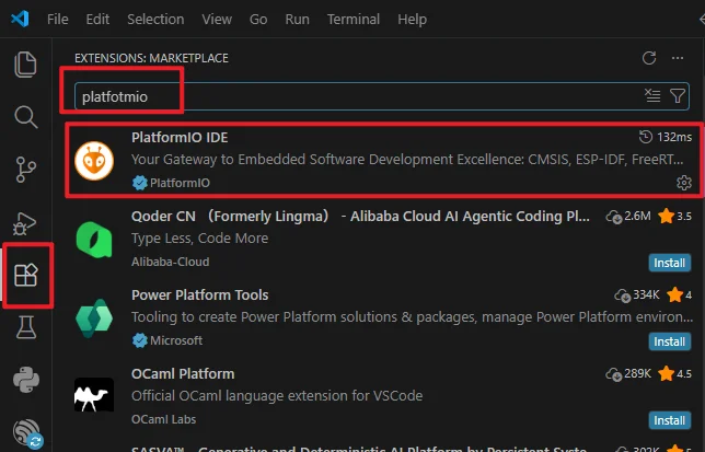
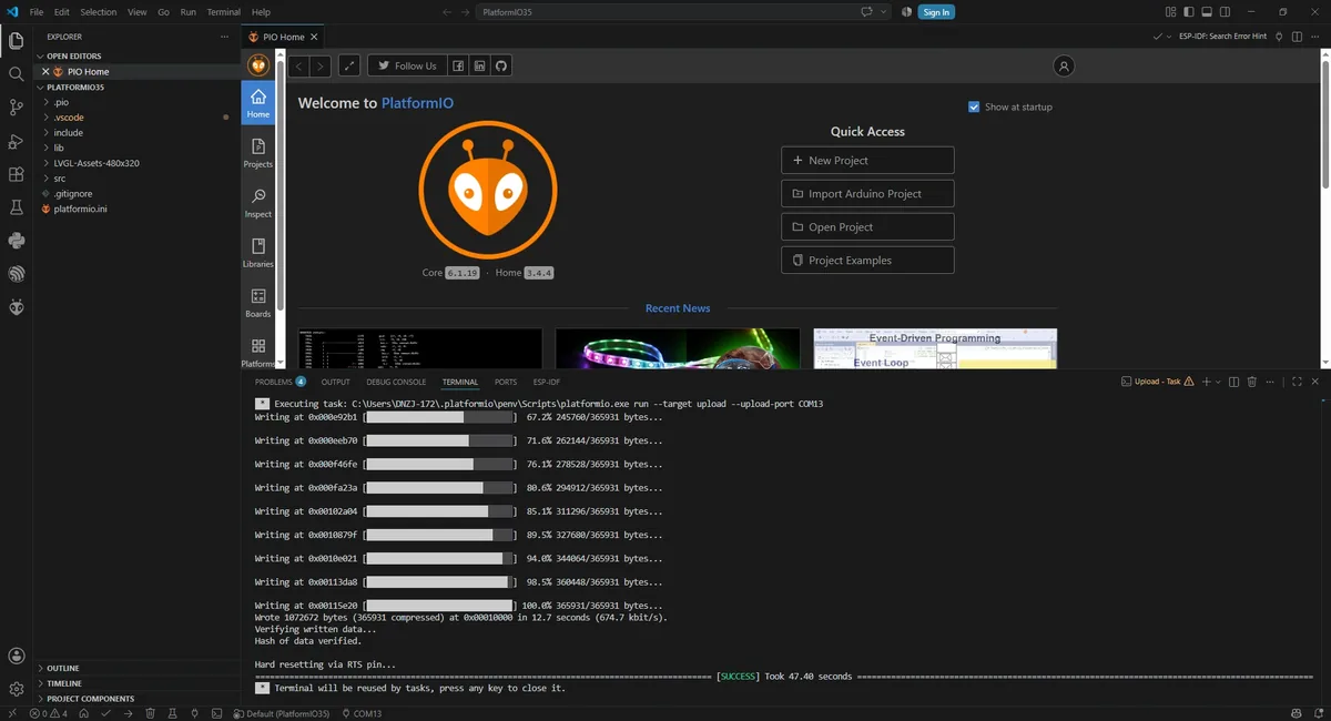
Open VS Code, search for and install PlatformIO IDE in Extensions.
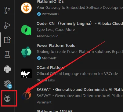
After installation, restart VS Code; the PlatformIO icon should appear on the left side. Click the icon to enter the PIO Home main page.
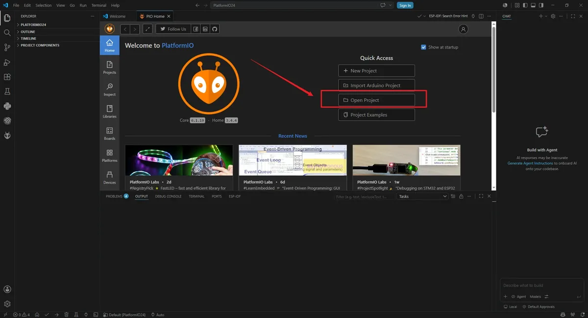
In the Quick Access area of PIO Home, click Open Project.
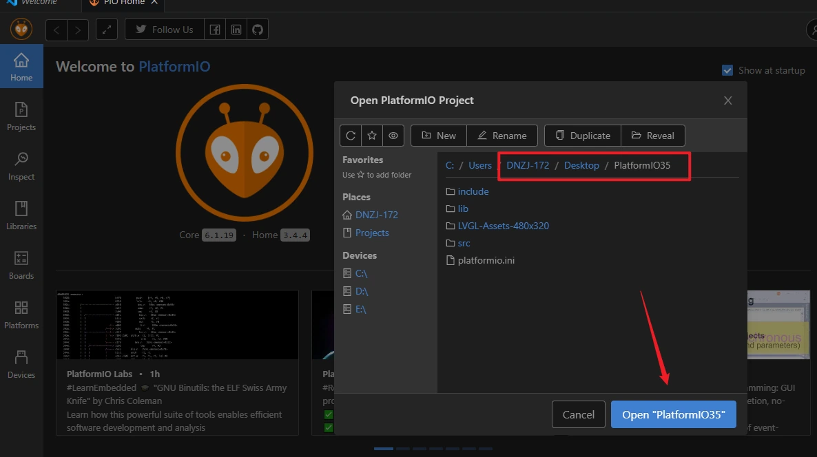
In the pop-up dialog, browse to the path, select the project root folder PlatformIO35 (the folder must contain platformio.ini), and click the blue button Open "PlatformIO35".
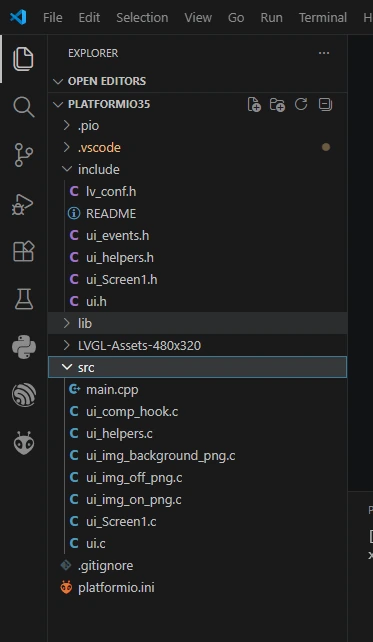
Load the project in the left-side Explorer
src/main.cpp: main program code.
platformio.ini: platform configuration file.
include and lib are dependency library directories.
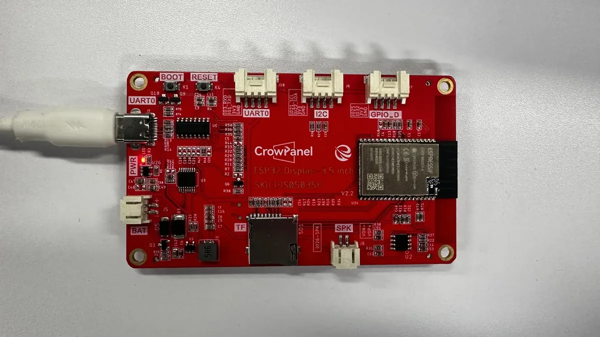
Connect the CrowPanel development board to a USB port on your computer using a USB data cable.
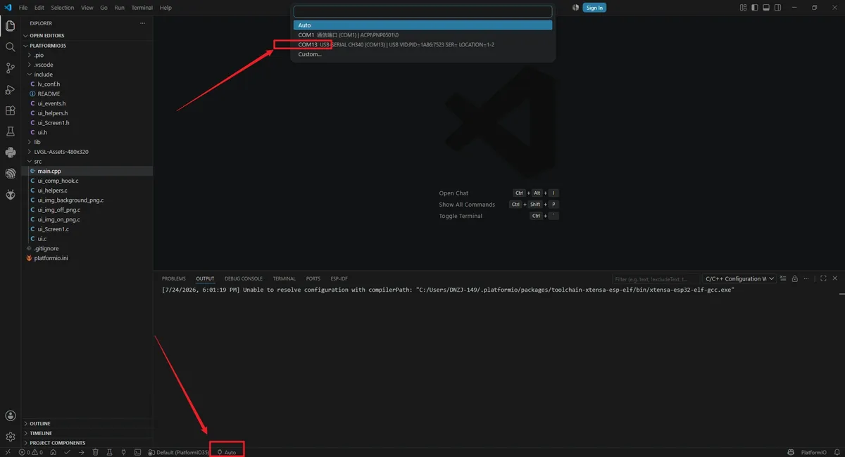
Select the device serial port: look at the bottom status bar of VS Code; the drop-down box on the left defaults to Auto. Click the drop-down box and select the serial port corresponding to the development board (example: COM13).
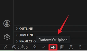
Click the right-arrow icon (PlatformIO: Upload) in the bottom status bar of VS Code. Wait for the build and upload process to execute automatically.
## 5. Hardware Operation Steps
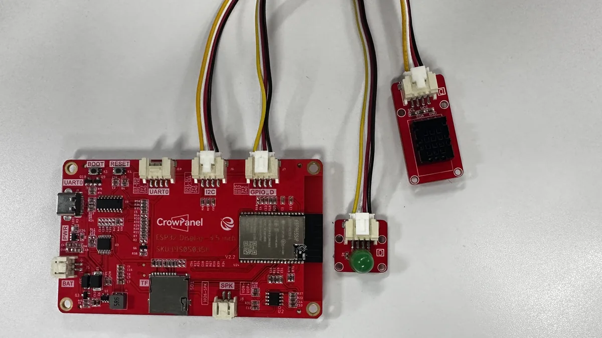
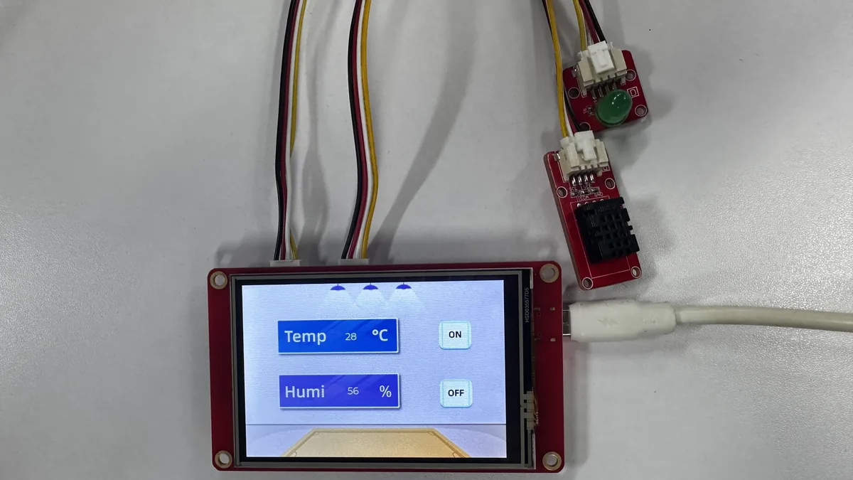
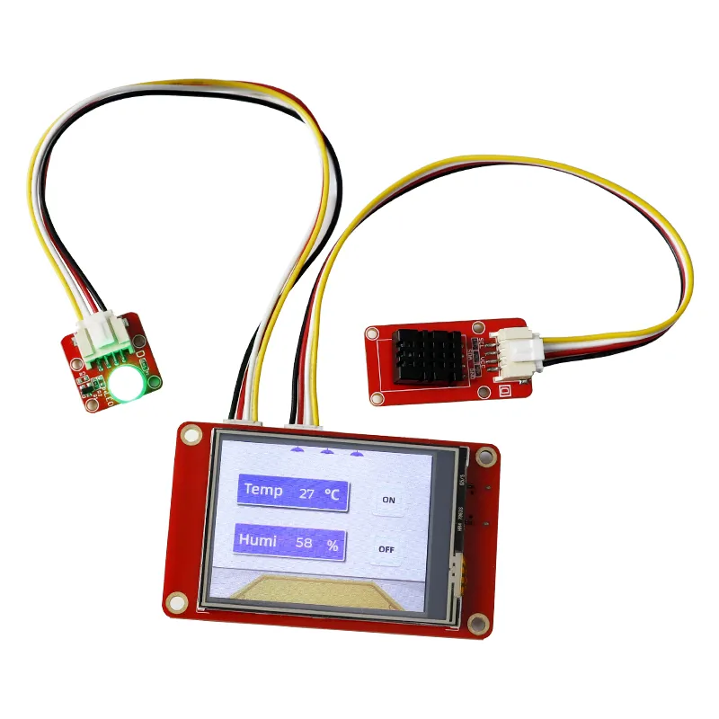
Wire the connections as shown in the diagram:
-
DHT20 temperature and humidity sensor → board I2C interface.
-
LED module → board GPIO_D interface.
It displays real-time temperature and humidity (data collected by the DHT20) and provides ON/OFF buttons to control the external LED on or off.
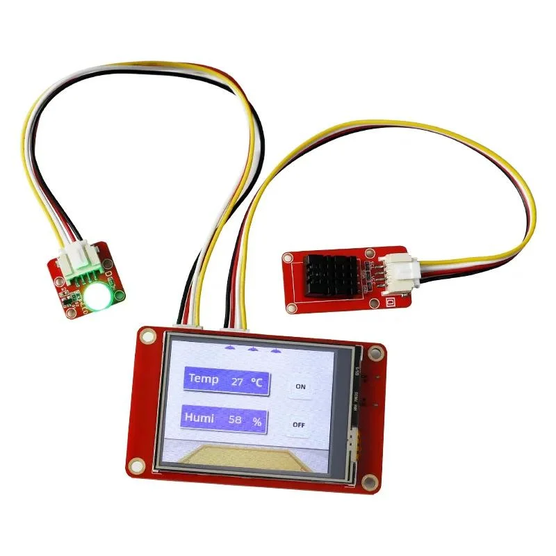
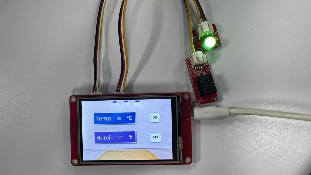
ON → LED lights up.
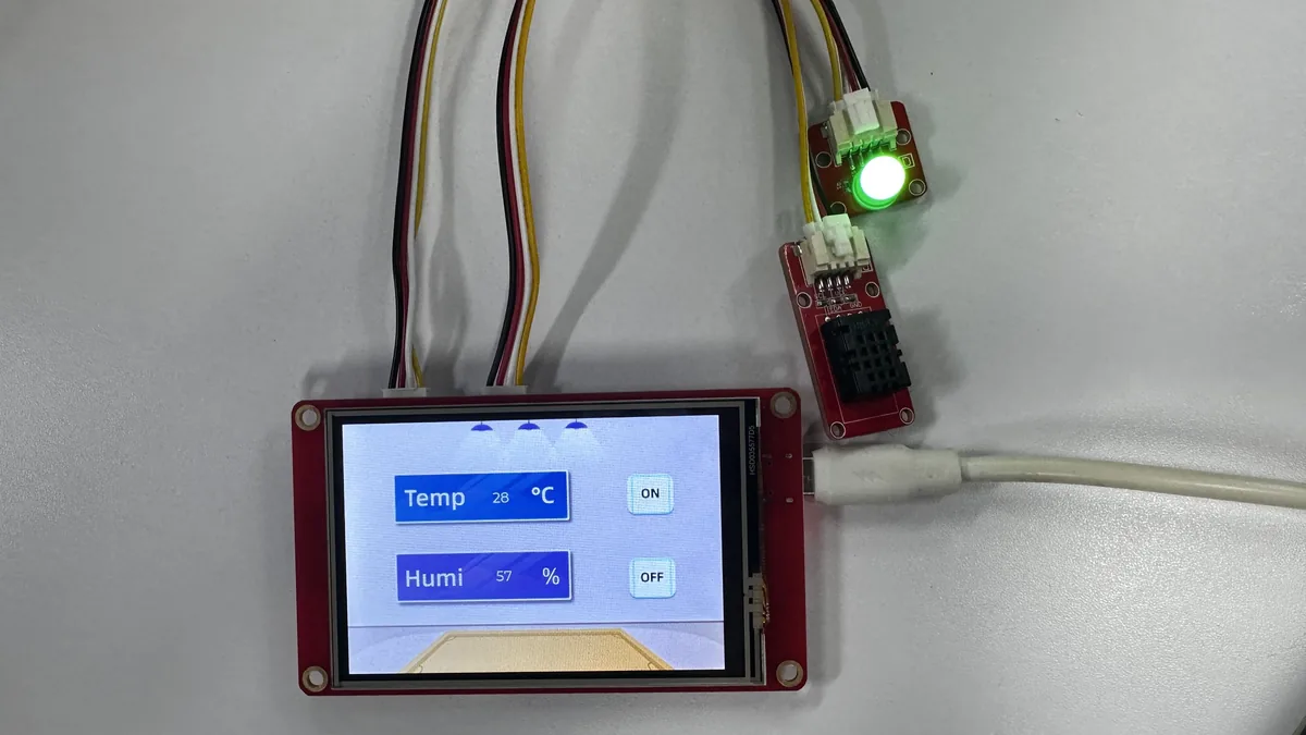
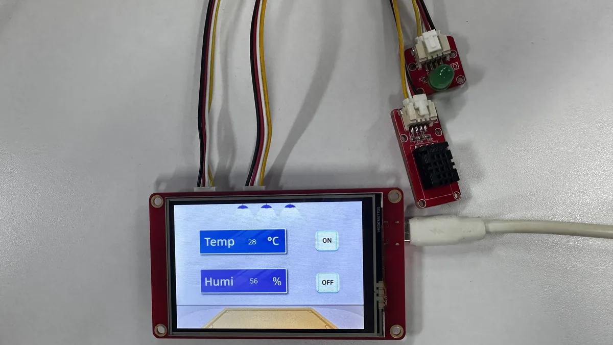
OFF → LED turns off.
6. Key Code Explanation
6.1 PlatformIO Environment and Dependency Pinning
[env:denky32]
; Use the pioarduino ESP32 platform release verified with this course.
platform = https://github.com/pioarduino/platform-espressif32/releases/download/55.03.38-1/platform-espressif32.zip

; Build for the ESP32 board profile used by the CrowPanel project.
board = denky32
framework = arduino

build_flags =
    ; Let LVGL load the project copy of include/lv_conf.h.
    -DLV_CONF_INCLUDE_SIMPLE
    -Iinclude

    ; Expose ESP32 GPIO register definitions required by the display library.
    -include soc/gpio_struct.h

; Lock the graphics libraries to the versions used by the annotated code.
lib_deps =
    lvgl/lvgl@9.1.0
    bodmer/TFT_eSPI@2.5.31
PlatformIO first reads platformio.ini and then prepares the ESP32 Arduino build environment. Here the pioarduino platform package, board, LVGL, and TFT_eSPI versions are pinned so that the course code uses verified APIs and display configurations. -DLV_CONF_INCLUDE_SIMPLE and -Iinclude let LVGL use the project's include/lv_conf.h instead of maintaining a configuration file in the .pio/libdeps generated directory over the long term.
6.2 LVGL Time Base and Partial Refresh
/**
 * @brief Return the millisecond time source required by LVGL.
 *
 * LVGL calls this callback whenever it advances timers and input processing.
 * PlatformIO's Arduino framework supplies the monotonic millis() counter.
 *
 * @param None.
 * @return Elapsed milliseconds since the board started.
 */
static uint32_t lv_tick_get_ms()
{
    return millis();
}
LVGL requires a stable millisecond time base to handle animations, timers, and input events. After this function is registered in setup() via lv_tick_set_cb(lv_tick_get_ms), LVGL can advance its UI tasks according to time.
/*---------------------------------------------------------------
 * Display geometry and rendering buffer
 * The buffer holds eight rows so LVGL can refresh the panel in small blocks.
 *--------------------------------------------------------------*/
static const uint16_t screenWidth  = 480;
static const uint16_t screenHeight = 320;

static lv_color_t buf1[screenWidth * 8];
The 3.5-inch screen has a landscape resolution of 480×320. The buffer holds only 8 rows of pixels, so LVGL refreshes the LCD in blocks—this completes the display while avoiding the large amount of RAM that a full-screen buffer would require at once.
6.3 Display Flush Callback
/**
 * @brief Transfer one rendered LVGL area to the LCD.
 *
 * LVGL calls this function after rendering a partial buffer. The final ready
 * notification allows LVGL to reuse the buffer for its next render operation.
 *
 * @param disp LVGL display that requested the transfer.
 * @param area Inclusive rectangle to refresh.
 * @param px_map RGB565 pixel data for the rectangle.
 * @return Nothing.
 */
void my_disp_flush(lv_display_t * disp, const lv_area_t * area, uint8_t * px_map)
{
    uint32_t w = (area->x2 - area->x1 + 1);
    uint32_t h = (area->y2 - area->y1 + 1);

    lcd.startWrite();
    lcd.setAddrWindow(area->x1, area->y1, w, h);
    lcd.pushColors(reinterpret_cast<uint16_t *>(px_map), w * h, true);
    lcd.endWrite();

    lv_display_flush_ready(disp);
}
LVGL does not operate the LCD directly; instead, it hands the rectangular area that needs updating to my_disp_flush(). setAddrWindow() specifies the write region, and pushColors() writes the RGB565 pixel data to the ILI9488. Finally, lv_display_flush_ready() must be called; otherwise LVGL will consider the buffer still occupied, and subsequent refreshes may stop.
6.4 Touch Input Callback
/**
 * @brief Read the calibrated touch state and pass it to LVGL.
 *
 * LVGL calls this function while polling the pointer input device. A pressure
 * threshold of 600 filters light contact; valid coordinates are printed so the
 * calibration can be checked before diagnosing UI events.
 *
 * @param indev LVGL input device requesting a sample.
 * @param data Output state and coordinate structure.
 * @return Nothing.
 */
void my_touchpad_read(lv_indev_t * indev, lv_indev_data_t * data)
{
    (void)indev;
    bool touched = lcd.getTouch(&touchX, &touchY, 600);

    if(!touched) {
        data->state = LV_INDEV_STATE_RELEASED;
    }
    else {
        data->state = LV_INDEV_STATE_PRESSED;

        // Pass calibrated pixel coordinates to the active LVGL input device.
        data->point.x = touchX;
        data->point.y = touchY;

        Serial.print("Data x ");
        Serial.println(touchX);

        Serial.print("Data y ");
        Serial.println(touchY);
    }
}
lcd.getTouch() converts the raw touch controller values into screen coordinates based on calData. When pressed, the program passes the coordinates to LVGL and also outputs a serial log, making it easy to determine whether the touch falls within the valid range of 0–479 and 0–319. If the UI is displayed but buttons do not respond, you should first check whether this callback is registered and whether the touch coordinates are correct, rather than modifying the UI widgets first.
6.5 Hardware Initialization and UI Creation
/*-------------------------------------------------------------
 * Prepare the controlled output and DHT20 I2C sensor
 * GPIO25 follows the UI button state; SDA22 and SCL21 feed the sensor.
 *------------------------------------------------------------*/
pinMode(25, OUTPUT);
digitalWrite(25, HIGH);

Wire.begin(22, 21);
dht20.begin();

lv_init();
lv_tick_set_cb(lv_tick_get_ms);

lcd.begin();
lcd.fillScreen(TFT_BLACK);
delay(300);
lcd.setTouch(calData);
// GPIO27 controls the LCD backlight on this board.
pinMode(27, OUTPUT);
digitalWrite(27, HIGH);
lcd.setRotation(1);
The initialization order is important: prepare the LED and I2C first, then initialize LVGL, the LCD, touch, and backlight. lcd.setRotation(1) sets the display orientation to landscape, which must match screenWidth = 480 and screenHeight = 320. Only after the backlight GPIO27 is pulled high can the LCD be seen.
// Create the LVGL display and connect its partial-render callback and buffer.
lv_display_t * disp = lv_display_create(screenWidth, screenHeight);
lv_display_set_flush_cb(disp, my_disp_flush);
lv_display_set_buffers(disp, buf1, NULL, sizeof(buf1), LV_DISPLAY_RENDER_MODE_PARTIAL);

// Register the calibrated touch callback as LVGL's pointer input device.
lv_indev_t * indev = lv_indev_create();
lv_indev_set_type(indev, LV_INDEV_TYPE_POINTER);
lv_indev_set_read_cb(indev, my_touchpad_read);

// Instantiate the SquareLine Studio screen and its controls after registration.
ui_init();
This code registers the LCD flush function and the touch read function with LVGL, and finally calls ui_init() to create the background, labels, and buttons exported from SquareLine Studio. If ui_init() is not executed, the backlight may be normal, but the UI objects will not appear.
6.6 Temperature/Humidity Labels and LED Output
/**
 * @brief Update sensor labels, apply button state, and service LVGL.
 *
 * PlatformIO calls this function repeatedly after setup(). Each pass reads the
 * DHT20, updates both generated labels, drives GPIO25 from led, and gives LVGL
 * time to render and process touch events.
 *
 * @param None.
 * @return Nothing.
 */
void loop()
{
    Serial.print(led);
    char DHT_buffer[12];
    int a = (int)dht20.getTemperature();
    int b = (int)dht20.getHumidity();
    snprintf(DHT_buffer, sizeof(DHT_buffer), "%d", a);
    lv_label_set_text(ui_Label1, DHT_buffer);
    snprintf(DHT_buffer, sizeof(DHT_buffer), "%d", b);
    lv_label_set_text(ui_Label2, DHT_buffer);

    if(led == 1) {
        digitalWrite(25, HIGH);
    }
    if(led == 0) {
        digitalWrite(25, LOW);
    }

    lv_timer_handler();
    delay(10);
}
The main loop continuously reads the DHT20, writing the temperature to ui_Label1 and the humidity to ui_Label2. The SquareLine event function modifies the global variable led when ON/OFF is clicked, and the main loop then converts led into the high or low level on GPIO25. lv_timer_handler() must run continuously; otherwise button events, redraws, and input processing will all stop.
7. UI Resource Creation and Integration
This section uses SquareLine Studio 1.6.1 to demonstrate the UI creation process again. The operation steps and illustrations refer to Elecrow's official SquareLine Studio tutorial. The course already provides the exported UI files, so beginners can first read this section to understand the workflow, then directly use the files in the project to complete the build. When creating a new project, you must select LVGL 9.1.0 and use a resolution of 480×320;
How to download SquareLine Studio: https://www.elecrow.com/wiki/Create_LVGL_UI_with_SquareLine_Studio.html.
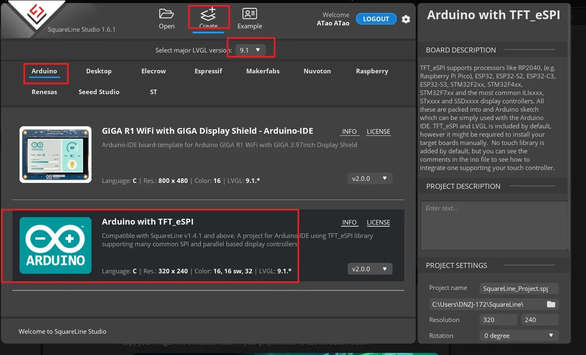
Launch SquareLine Studio 1.6.1, click Create, and select the Arduino with TFT_eSPI template for the Arduino platform. This template is responsible for generating the UI file framework suitable for Arduino and TFT_eSPI projects.
Note: When the Arduino framework is selected, SquareLine Studio displays only the Arduino with TFT_eSPI option. It generates template code suitable for TFT_eSPI, but SquareLine Studio also supports other graphics libraries; when switching to different hardware, you need to modify the display code according to the actual library.
Enter the project name, set the LVGL version to 9.1.0, set the resolution to width 480 and height 320, set the color depth to 16 bit, then click CREATE. After creation, the canvas should be in landscape orientation at 480×320.
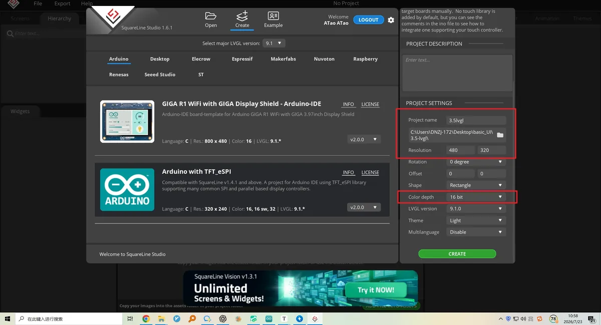
- Note: A
16 bitcolor depth can represent 65,536 colors using an RGB 5:6:5 pixel format. Keep it consistent with the project's color configuration.
After the project opens, select Screen1 in the Screens panel on the left, and confirm that the central canvas is blank and that the Inspector on the right shows the Screen properties. All subsequent widgets will be added to this page.
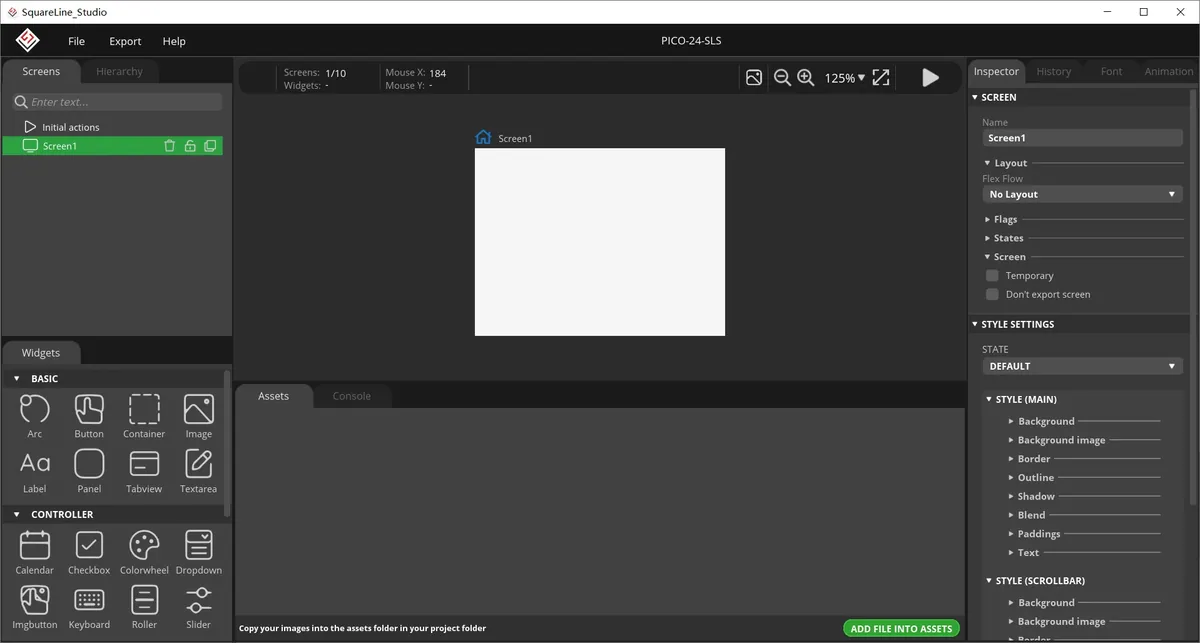
In the Assets area, click ADD FILE TO ASSETS, and import background.png, on.png, and off.png from LVGL-Assets-480x320/ in sequence. After import, you should see three thumbnails.
Material link:
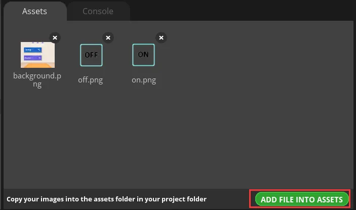
Note: Image assets support only the PNG format; the pixel dimensions of an image should be smaller than the project screen size; a single image should not exceed 100 KB, and preferably kept within 30 KB, to avoid affecting display smoothness.
Select Screen1, expand STYLE SETTINGS > STYLE (MAIN) > Background on the right, and enable the background image setting.
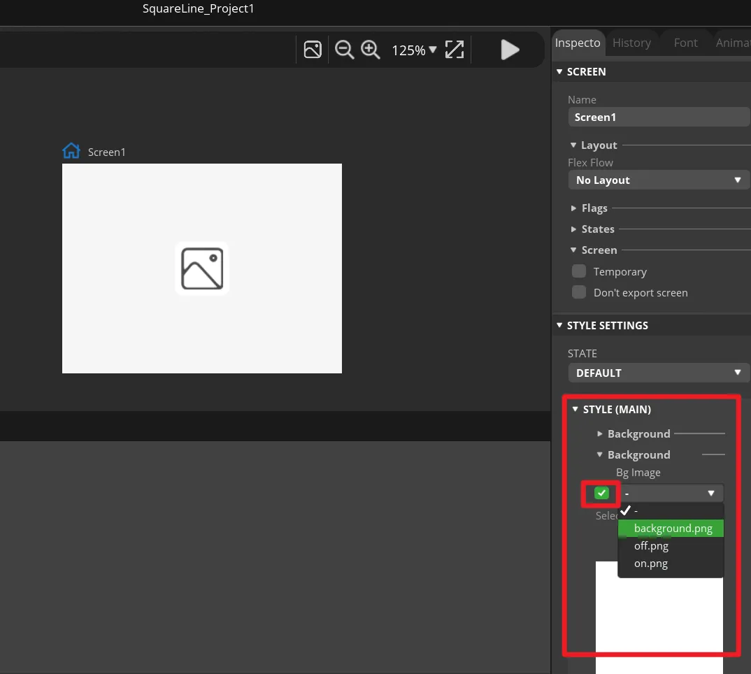
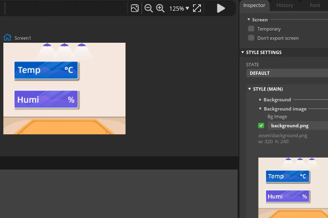
In Bg Image, select background. The canvas should immediately display the course background image, and the background should fully cover the 480×320 page.
In the Widgets panel on the left, click Label to add Label1 to Screen1. This label will be updated by the program to show the temperature value.
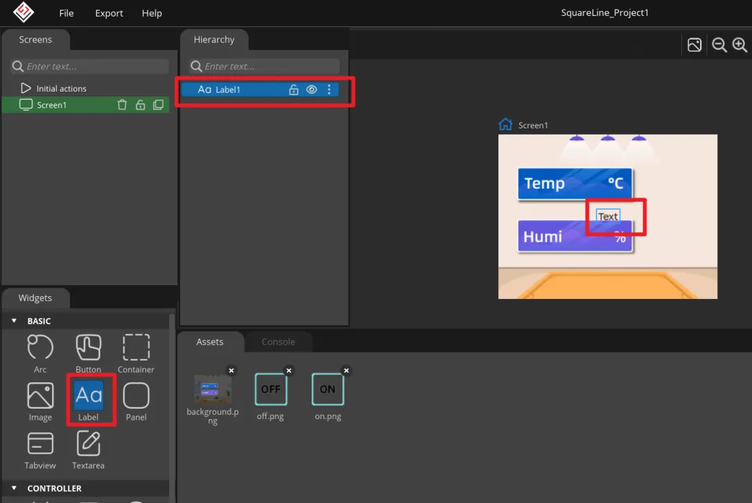
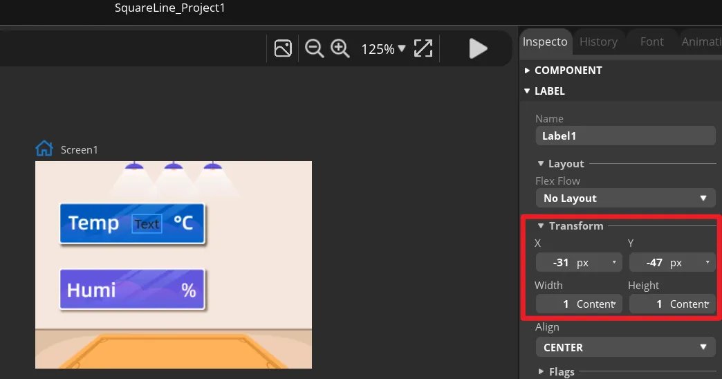
Select Label1, and in Transform adjust the X and Y position and the width and height so that it sits within the temperature display area of the background image. You can also drag it first and then fine-tune using the numeric values.
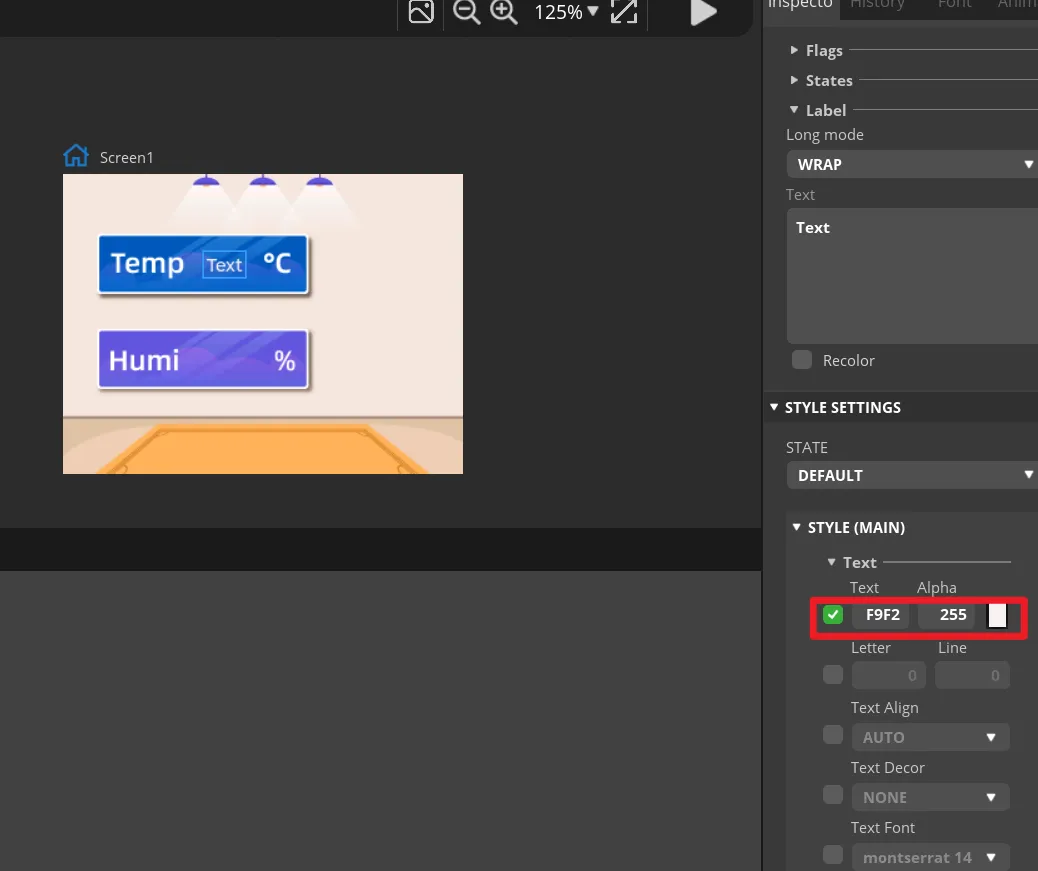
In the STYLE (MAIN) of Label1, change the text color to white and set an appropriate font size. The text on the canvas should be clearly visible and should not overflow the background frame.
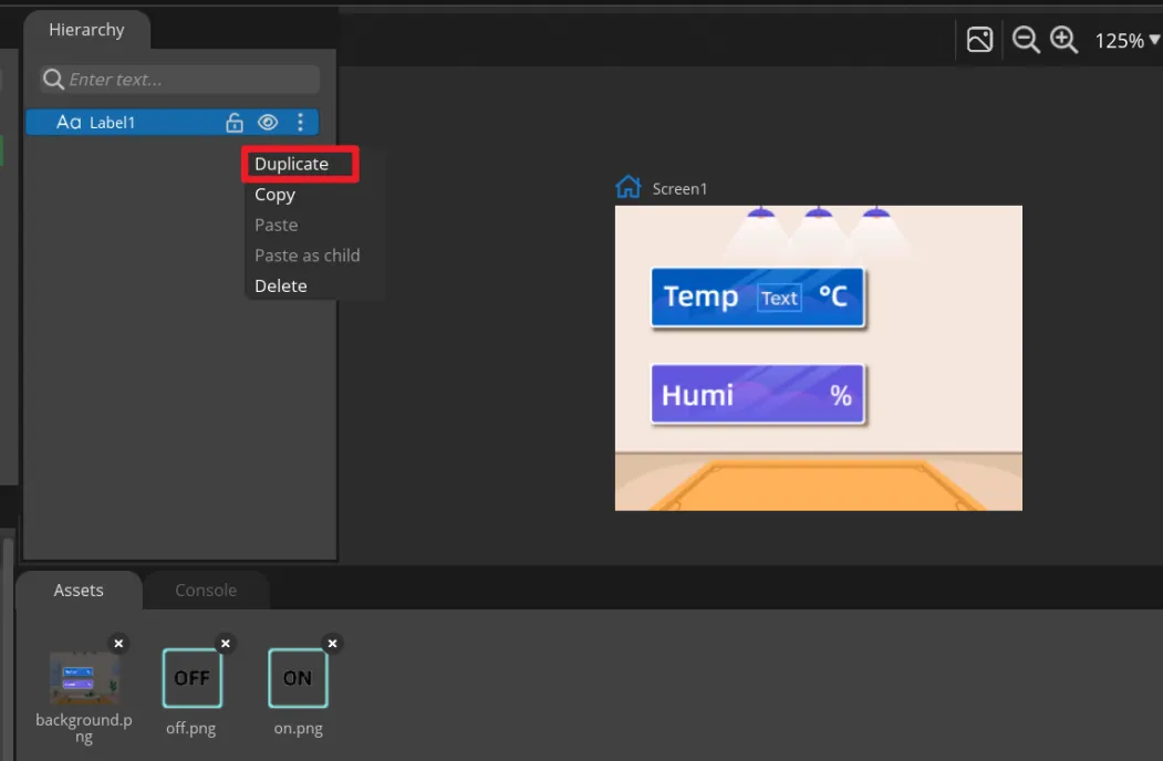
Right-click Label1 and select Duplicate to create Label2, then move it to the humidity display area. Keep the names Label1 and Label2, because the main program updates them by name.
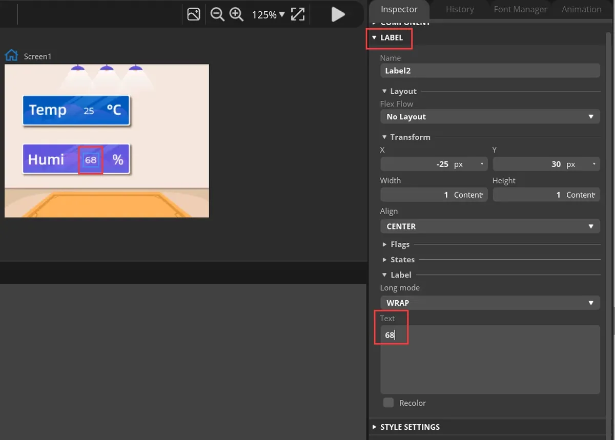
Select each of the two labels and enter default numbers in Text for easy previewing. These are only design-time placeholder values; once the board is running, they will be replaced by DHT20 readings.
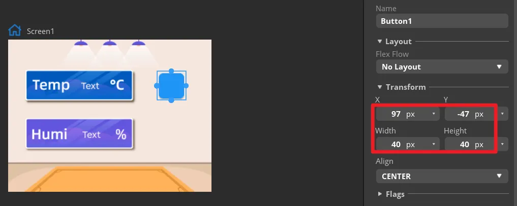
In Widgets, click Button to add Button1, and drag it to the ON area on the right side of the interface.

In Transform, configure the size of Button1 and adjust its position so that the button aligns with the ON area in the background.
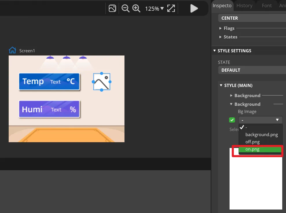
Expand Button1's STYLE (MAIN) > Background, and select on.png as the background image. The ON icon should appear on the canvas.
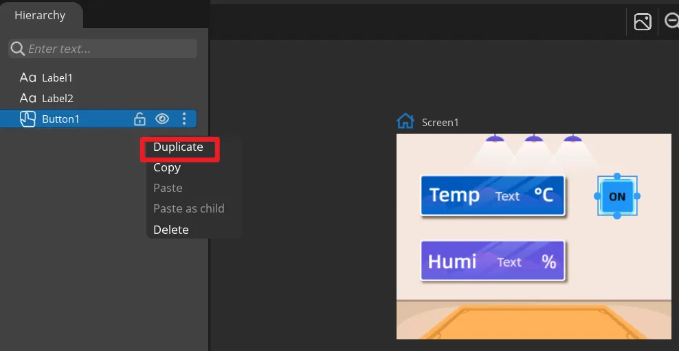
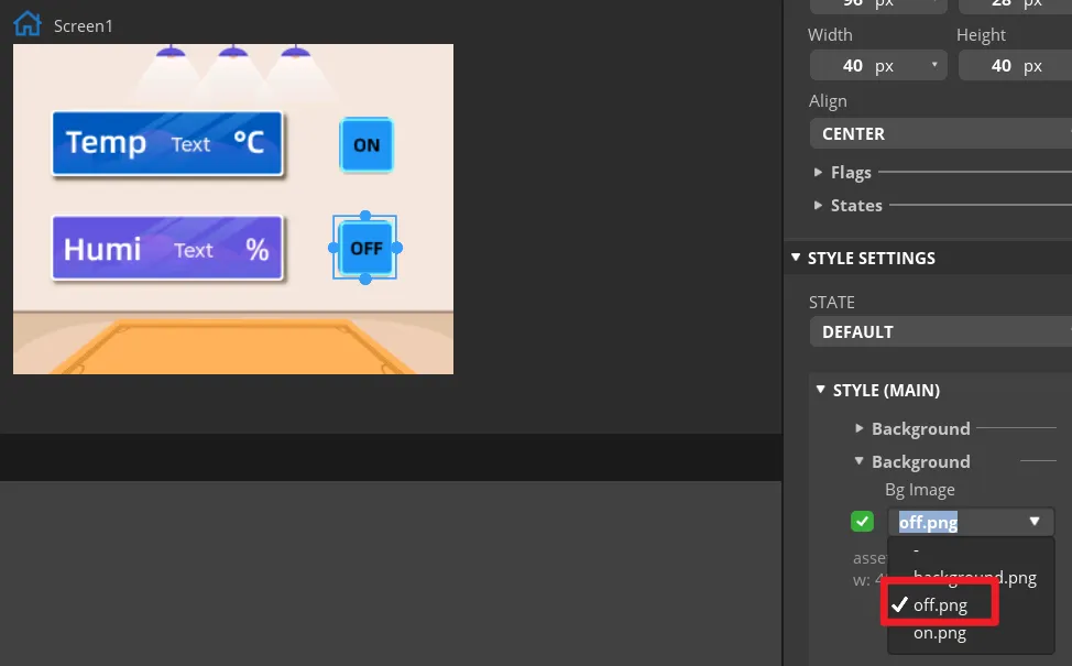
Duplicate Button1 to get Button2, move it to the OFF area, and change the background image to off.png. Keep the names Button1 and Button2 so they correspond to the exported event functions.
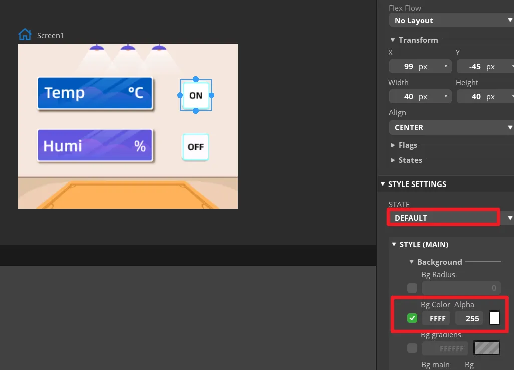
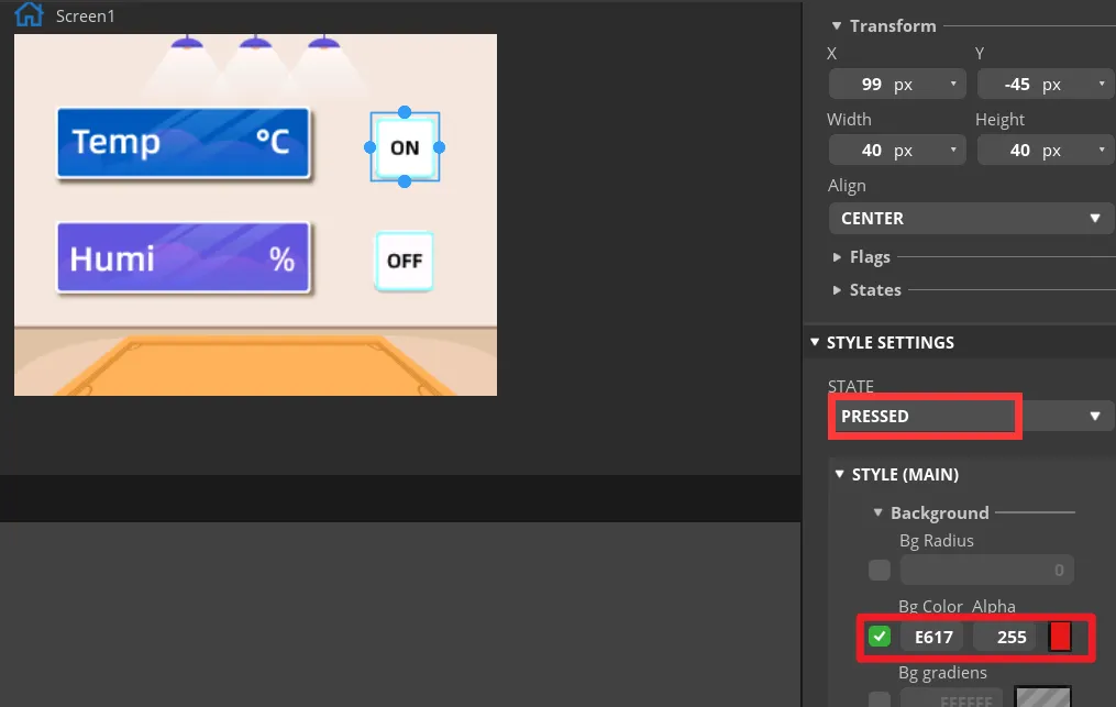
In the STATE settings of both buttons, check the DEFAULT and PRESSED states. The pressed state may use a distinct color change so that, when previewing, you can tell whether a button is pressed. In "Inspector" -> "Style Settings" -> "State", set the displayed background color to white, and when in the "fixed state" display red. Configure the same parameters for the "OFF" button.
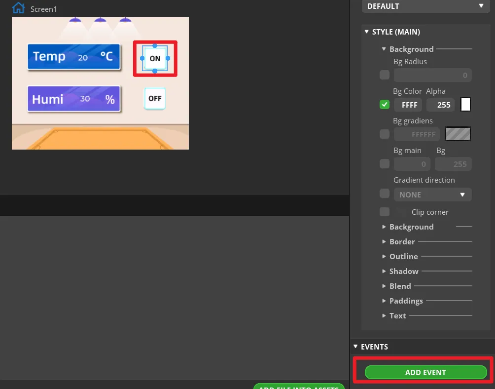
Select Button1 and click ADD EVENT.
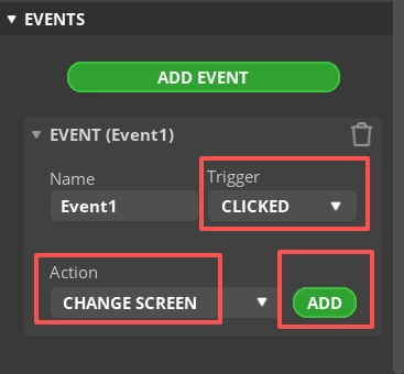
Select "CLICKED" as the trigger condition, and in "Action" choose a trigger event. This will be modified later in the generated program to implement the LED control function.
Note: Since the button is ultimately meant to control the LED on/off, you can add any event here first, so that the exported UI file generates the button event code framework; the LED control code will be modified in a later step.
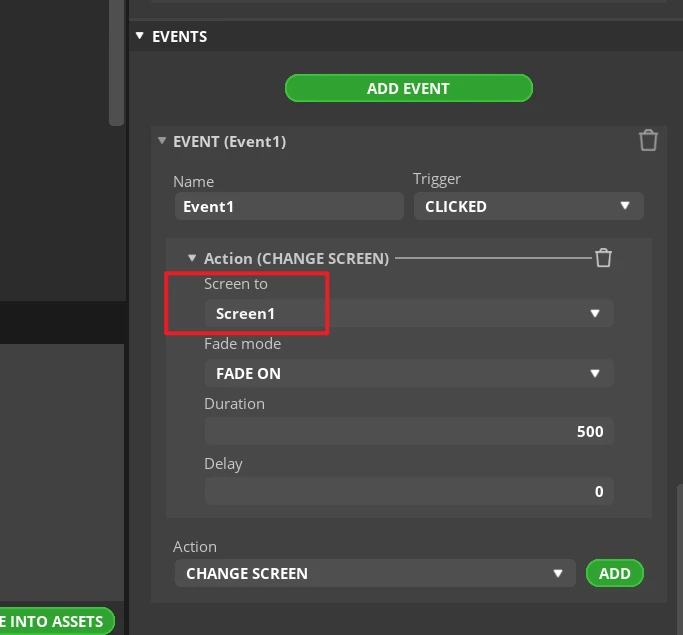
Complete this event. Here, I choose to switch screens, that is, switch to the Screen1 screen.
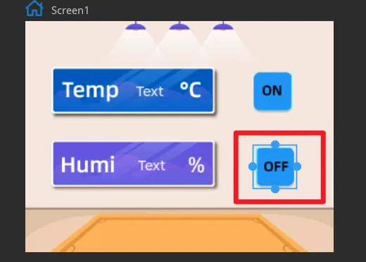
Add the event to Button2 in the same way (state is "OFF").
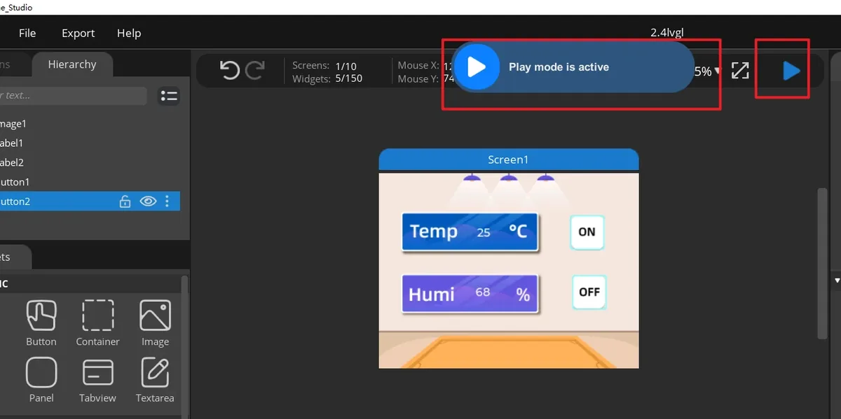
Click Run.
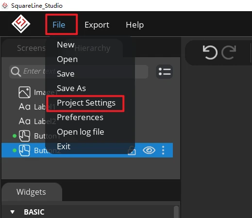
Open File > Project Settings, then configure the relevant settings for the exported files.
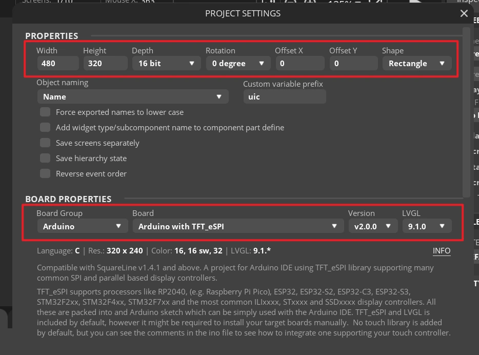
Set the export directory to an easy-to-find English-only path, create a new output folder, fill in and confirm that the LVGL Include Path is lvgl.h, and after confirming, click APPLY CHANGES.
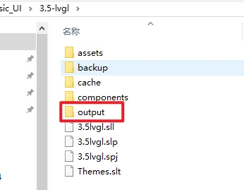
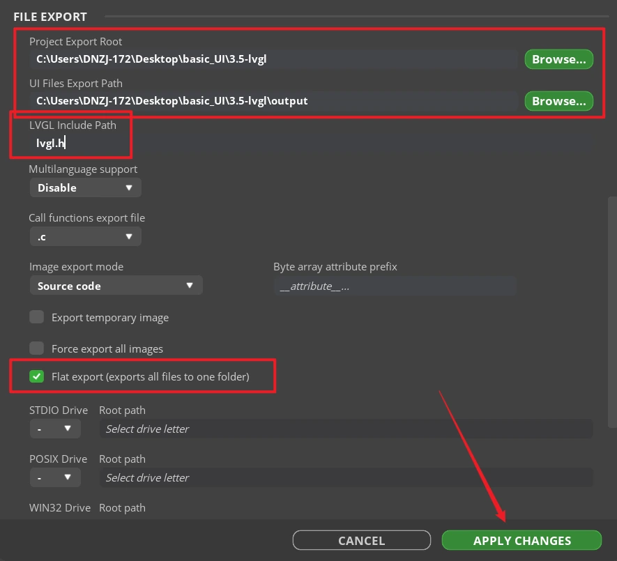
Tip: After selecting Flat export, all output files are placed in the same folder, and the program does not need to modify file paths again. If Flat export is not selected, files are scattered across different folders, and the compiler may not be able to recognize them automatically, usually requiring manual path modifications; therefore, it is recommended to keep it checked.
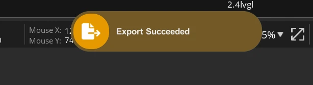
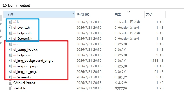
Click Export > Export UI Files. After the export completes, ui.c, ui.h, ui_Screen1.c, the event files, helper files, and image array files should appear in the target directory.
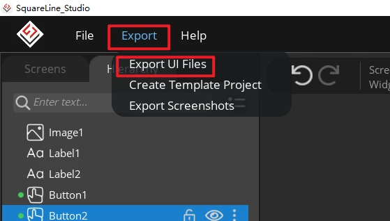
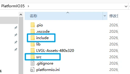
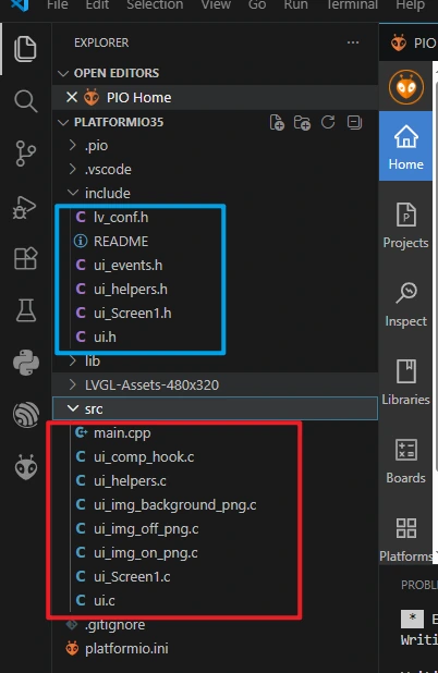
Add the UI files to the PlatformIO project. We need to add the UI files from SquareLine Studio to the PlatformIO project. The .c files of the user interface should be placed in the /scr folder of the project files, while the .h files should be placed in the /include folder.
8. Expected Behavior
After the firmware is uploaded and reset, the LCD is first cleared to black, and about 300 ms later the backlight turns on and loads the 320×240 UI. The background image should be displayed in full, two white integers appear slightly left of the center of the screen, and the ON and OFF icons appear on the right. When the DHT20 is connected properly, the two integers are updated with the temperature and humidity readings, respectively.
ON -> LED lights up.
OFF -> LED turns off.
9. Code Download
- PlatformIO project: PlatformIO35.