ESP-IDF_LVGL: 7.0-inch ESP32-S3 Environment Monitoring and Touch Control
1. Course Introduction
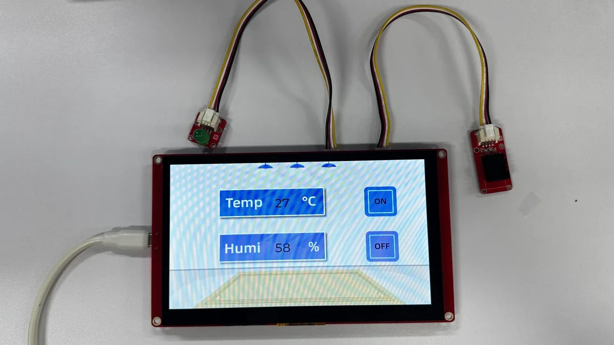
In this lesson, we use the Arduino-as-component approach within an ESP-IDF project to run setup()/loop(). The 800×480 RGB display is driven by Arduino_GFX, touch input is provided by GT911, the UI is built with LVGL 9, and DHT20 supplies temperature and humidity data. After the program starts, the lesson UI is displayed; tapping a button changes the GPIO38 output, and the serial output shows initialization, touch coordinates, sensor readings, and output status.
Reference materials:
2. Learning Objectives
- Be able to identify ESP-IDF component dependencies and the entry-point relationship of Arduino-as-component.
- Be able to complete ESP32-S3 project configuration, compilation, flashing, and monitor operations.
- Be able to explain LVGL partial buffering, Arduino_GFX screen refresh, and GT911 input callbacks.
- Be able to evaluate experimental results based on the display, touch, DHT20, and GPIO38 behavior.
3. What You Need to Prepare
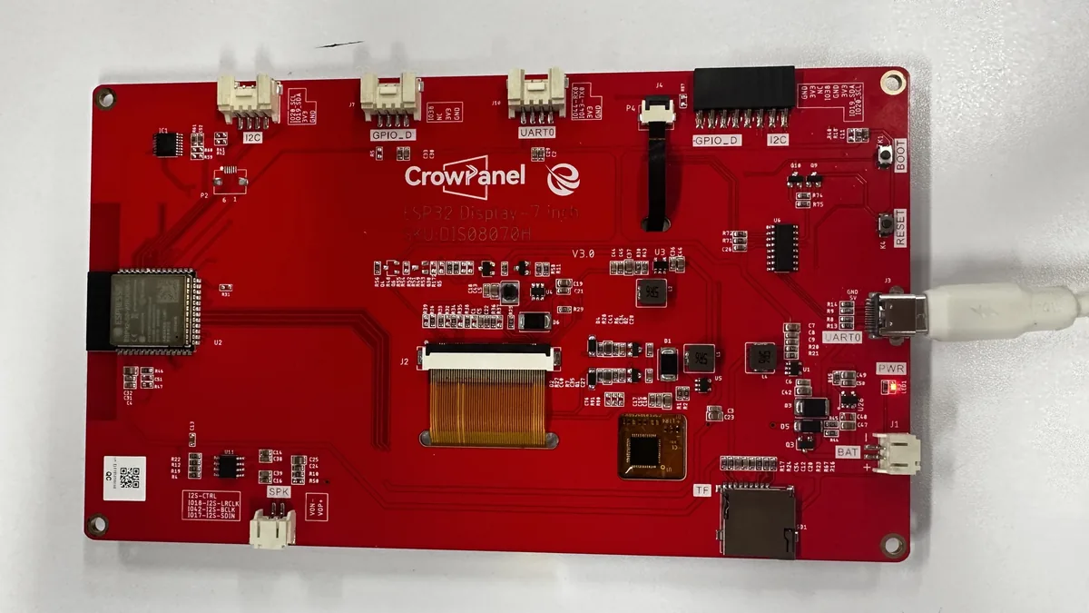
- CrowPanel ESP32 7.0-inch HMI and a USB data cable.
- One DHT20 temperature and humidity module, connected to GPIO19 (SDA) and GPIO20 (SCL).
- One LED module, connected to GPIO38.
- VS Code, the Espressif IDF extension, and ESP-IDF 5.5.4, or an ESP-IDF 5.5.4 terminal with
export.ps1already sourced. - VS Code + ESP-IDF Extension: Click here for the installation tutorial.
- The complete project
LVGL_Control_LED_70. - On Windows, it is recommended to copy the project to a short path containing only ASCII characters, for example
C:/work/LVGL_Control_LED_70. The Kconfig/CMake tools in ESP-IDF 5.5.4 may generate garbled temporary paths under some Chinese-language paths. - The
main/idf_component.ymldeclaresespressif/arduino-esp32: ^3.3.10; do not mix it with standalone Arduino IDE libraries. - Keep
components,managed_components,sdkconfig.defaults,partitions.csv, and the UI resources fully intact.
4. Software Operation Steps
The steps below are mainly performed using the Espressif IDF extension in VS Code. On first use, please follow them in order; do not flash directly before the target chip and serial port have been set.
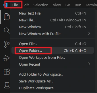
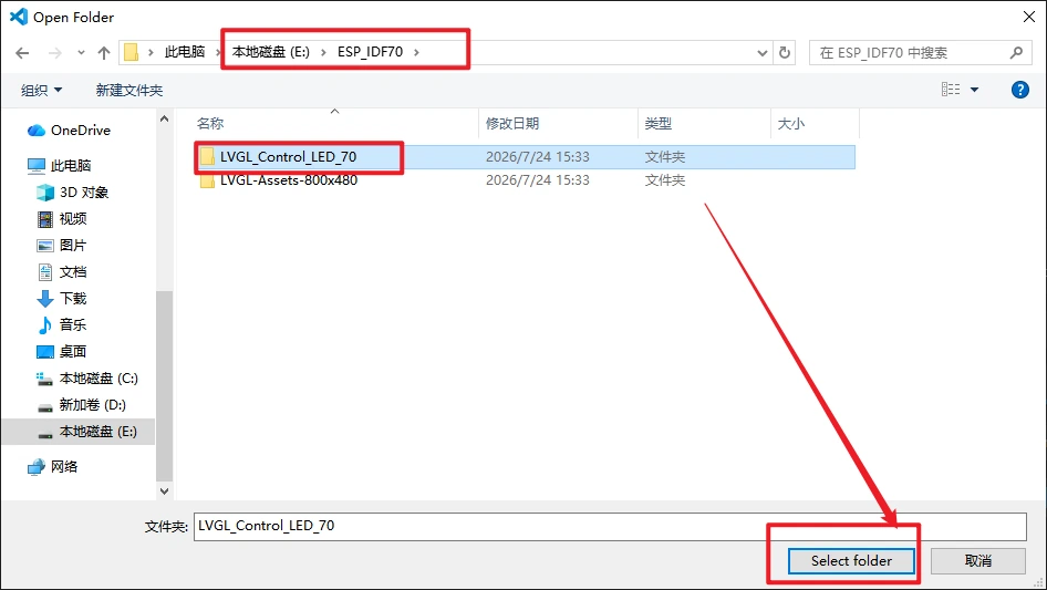
In VS Code, select File > Open Folder to open the project.
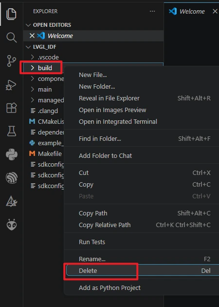
Run the Build-> Delete command to completely clear the build cache and path files left behind by old projects, avoiding compilation conflicts.
Make sure ESP-IDF 5.5.4 is installed.

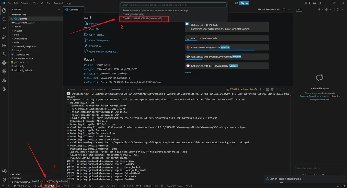
Connect the board with a USB data cable, click the port name in the status bar, and select the COM port that actually appears for the board. The port number varies by computer; if you are unsure, unplug the board and watch which port disappears from the list.
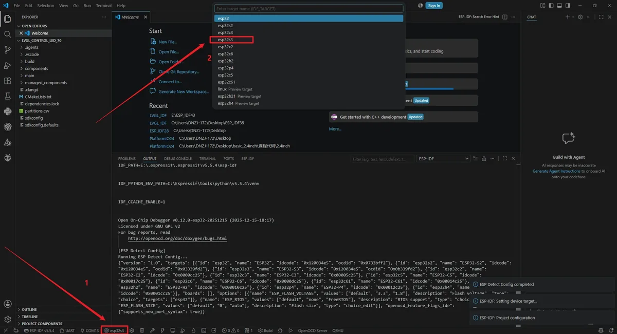
Click the chip icon in the VS Code status bar, run ESP-IDF: Set Espressif Device Target, and select esp32s3 to set the target chip.
For the OpenOCD configuration, select ESP32-S3 chip (via builtin USB-JTAG) to avoid the plugin repeatedly popping up a missing-configuration prompt.

Before starting to compile the code, we need to perform SDK configuration first. Only after setting up the relevant configurations required for this project can the code be compiled successfully.
Click on SDK configuration.

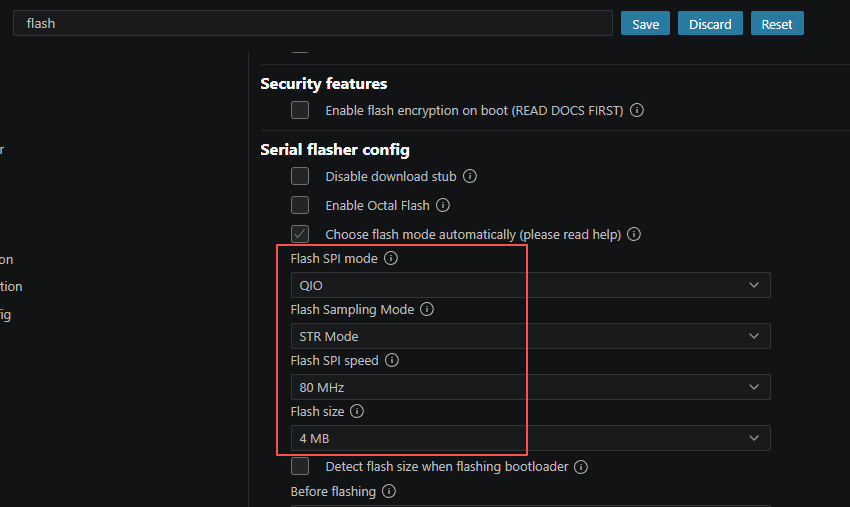
Then, after the configuration interface opens, search for "flash" and modify the options here to be the same as mine.
After making the modifications, be sure to click "Save" to save your changes.
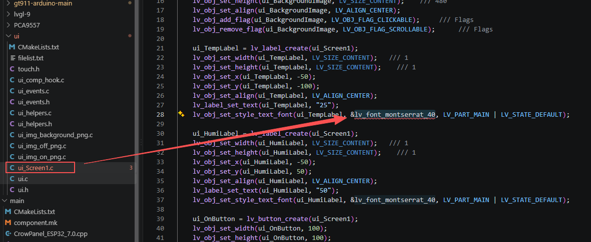
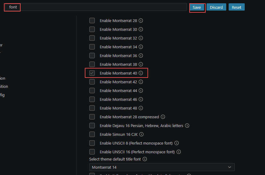
Then search for "font" and activate the font size we used in the code. Only in this way can this font be used in the code project.
After making the modifications, be sure to click "Save" to save your changes.
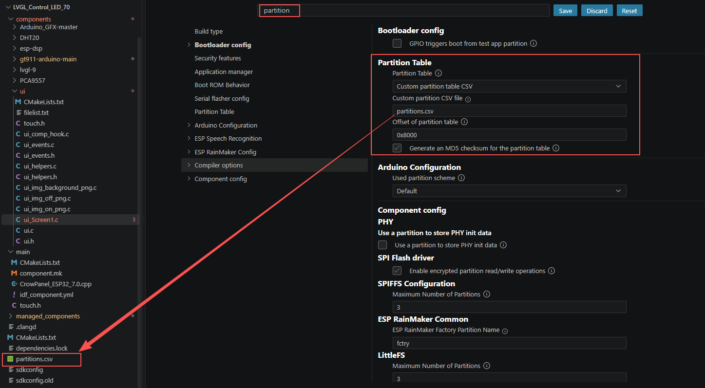
Then search for "partition", and set the partition table files used in our project. This will prevent the code from failing to compile due to its excessive size.
After making the modifications, be sure to click "Save" to save your changes.
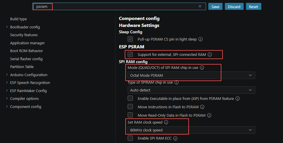
And we also need to enable "PSRAM", otherwise the code will fail to compile.
After making the modifications, be sure to click "Save" to save your changes.
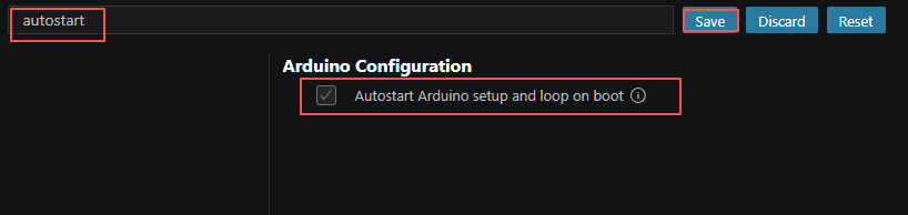
Since our ESP-IDF code uses the syntax of Arduino IDE, we also need to enable "Autostart" in the SDK configuration.
After making the modifications, be sure to click "Save" to save your changes.
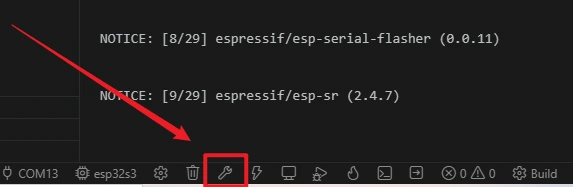
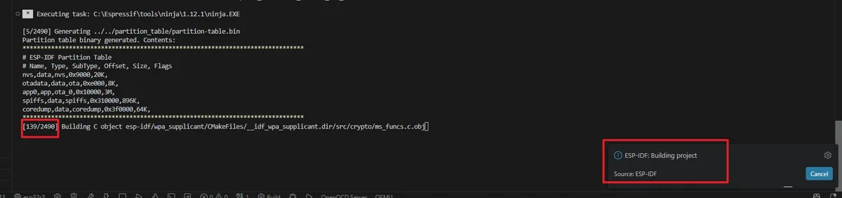
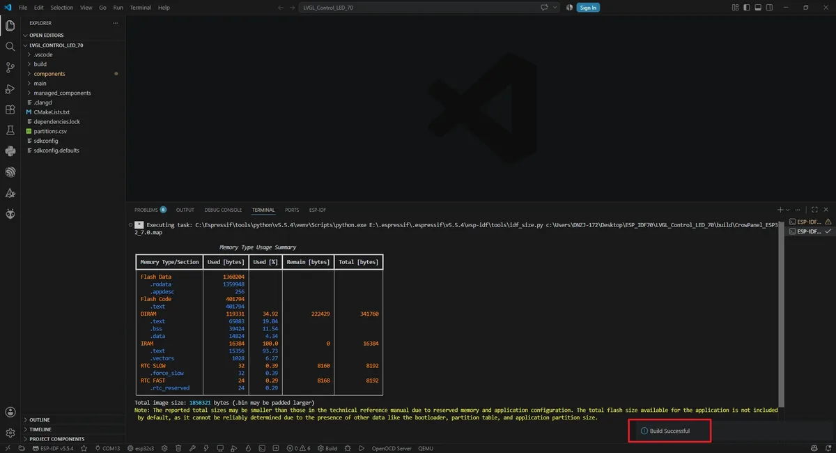
Click the Build (wrench) button in the status bar, or run idf.py build in the terminal. The first build takes longer; a notification in the bottom-right corner should indicate that the project build is complete.
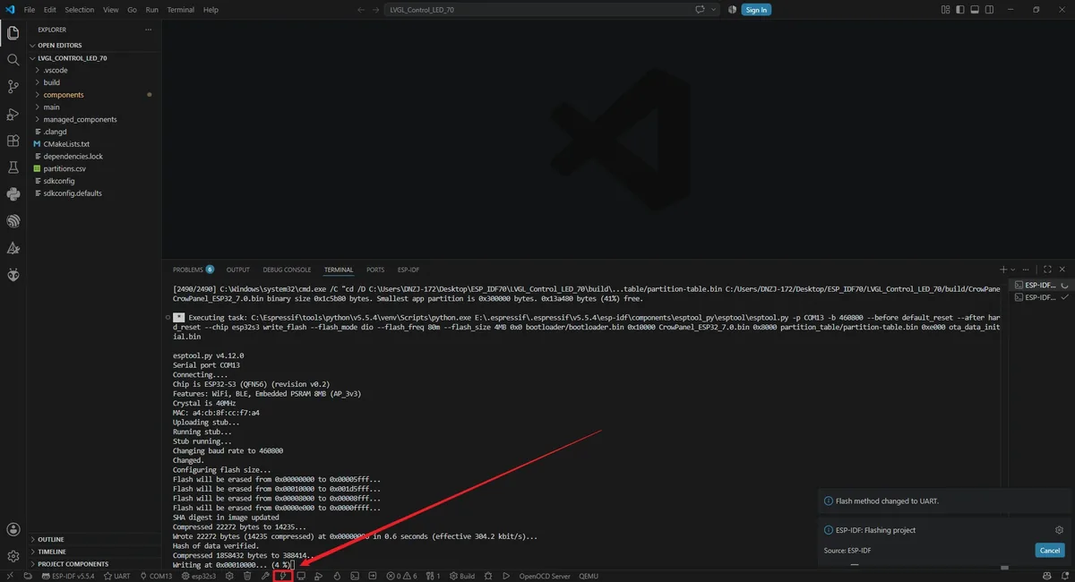
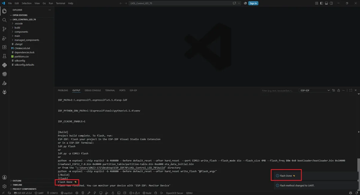
Confirm that the flashing method in the status bar is UART, then click the lightning-shaped Flash button; you can also run idf.py -p COMx flash, replacing COMx with the actual port. After writing finishes, the board resets automatically.
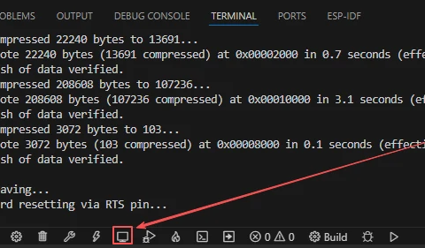
After uploading the code, click the Monitor button to open the serial port monitor; the baud rate is set to 115200 by default. After the monitor is opened, it should first display the ESP-IDF startup information, and then continuously print the serial port printing information set in your code.
5. Hardware Operation Steps
With the power off, connect the DHT20 module to the board's IIC interface, and connect the LED module to the interface labeled GPIO_D.
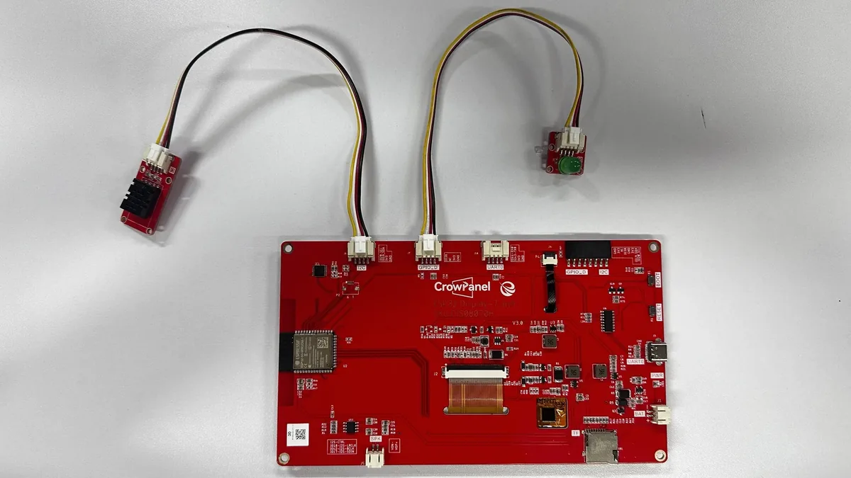
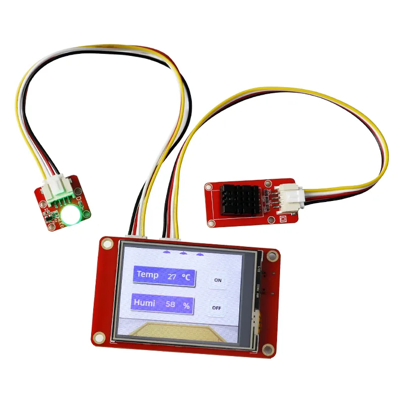
Reconnect a USB cable that supports data transfer. After uploading finishes and the board resets automatically, the screen backlight should turn on, and the UI should show temperature, humidity, and two buttons labeled ON and OFF.
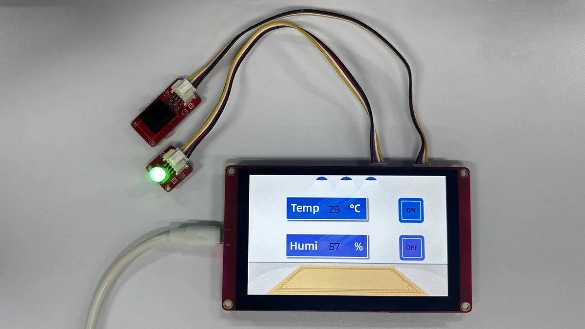
- Tap ON with your finger, and observe the UI response and the GPIO38 output state; do not touch the screen with sharp or conductive objects.
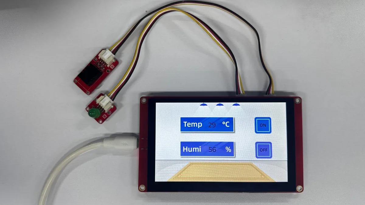
- Tap OFF, and confirm that the output returns to a low level and the LED turns off.
6. Key Code Explanation
6.1 Arduino Compatibility Layer and RGB Display
/*---------------------------------------------------------------
 * RGB display hardware description
 * Bind the ESP32-S3 RGB signals and panel timing to Arduino_GFX.
 *--------------------------------------------------------------*/

// Partial-render buffer shared by LVGL and the RGB display driver.
static lv_color_t *lvgl_draw_buf = nullptr;

Arduino_ESP32RGBPanel *bus = new Arduino_ESP32RGBPanel(
    41 /* DE */, 40 /* VSYNC */, 39 /* HSYNC */, 0 /* PCLK */,
    14 /* R0 */, 21 /* R1 */, 47 /* R2 */, 48 /* R3 */, 45 /* R4 */,
    9 /* G0 */, 46 /* G1 */, 3 /* G2 */, 8 /* G3 */, 16 /* G4 */, 1 /* G5 */,
    15 /* B0 */, 7 /* B1 */, 6 /* B2 */, 5 /* B3 */, 4 /* B4 */,
    0 /* hsync_polarity */, 40 /* hsync_front_porch */, 48 /* hsync_pulse_width */, 40 /* hsync_back_porch */,
    0 /* vsync_polarity */, 1 /* vsync_front_porch */, 31 /* vsync_pulse_width */, 13 /* vsync_back_porch */,
    1 /* pclk_active_neg */, 16000000 /* prefer_speed */, false /* useBigEndian */,
    0 /* de_idle_high */, 0 /* pclk_idle_high */, 800 * 10 /* bounce_buffer_size_px */
);
The project uses the Arduino-as-component approach in ESP-IDF, and the main file still keeps setup() and loop(). The DE, VSYNC, HSYNC, PCLK, RGB data lines, and porch parameters of the RGB bus must match the 7.0-inch 800×480 panel; if you copy parameters from a tutorial for a different size, the common symptoms are a black screen, color shift, scrolling image, or a mismatch between the touch position and the displayed image.
6.2 LVGL Partial Buffering
// Display dimensions are read from the panel after initialization.
static uint32_t screenWidth;
static uint32_t screenHeight;

// A 20-line DMA buffer lets LVGL render in small strips instead of
// reserving a full 800 by 480 frame buffer in internal memory.
const size_t draw_buf_pixels = screenWidth * 20;
lvgl_draw_buf = (lv_color_t *)heap_caps_malloc(
    draw_buf_pixels * sizeof(lv_color_t), MALLOC_CAP_INTERNAL | MALLOC_CAP_DMA);
lv_display_set_buffers(display, lvgl_draw_buf, NULL,
                       draw_buf_pixels * sizeof(lv_color_t),
                       LV_DISPLAY_RENDER_MODE_PARTIAL);
Here only 20 rows of pixels are allocated as the DMA buffer to reduce memory usage; LVGL calls my_disp_flush() in chunks, and then Arduino_GFX writes them to the RGB display. If buffer allocation fails, the program halts in an error loop; you should first check the memory configuration, color depth, and whether a memory region suitable for 800×480 refresh is enabled.
6.3 Screen Refresh Callback and Touch Callback
/**
 * @brief Transfer one LVGL render area to the physical display.
 * @param display LVGL display requesting the transfer.
 * @param area Updated rectangle in display coordinates.
 * @param pixel_map RGB565 pixels produced by LVGL.
 * @return Nothing.
 * @note Called by LVGL whenever a render buffer is ready.
 */
void my_disp_flush(lv_display_t *display, const lv_area_t *area, uint8_t *pixel_map)
{
    uint32_t w = (area->x2 - area->x1 + 1);
    uint32_t h = (area->y2 - area->y1 + 1);

    lcd->draw16bitRGBBitmap(area->x1, area->y1, reinterpret_cast<uint16_t *>(pixel_map), w, h);

    lv_display_flush_ready(display);
}

lv_indev_t *indev = lv_indev_create();
lv_indev_set_type(indev, LV_INDEV_TYPE_POINTER);
lv_indev_set_read_cb(indev, my_touchpad_read);
lv_indev_set_display(indev, display);
my_disp_flush() is responsible for writing the local region rendered by LVGL to the screen, and calls lv_display_flush_ready() when done. After the input device is registered, LVGL periodically calls my_touchpad_read(). When the UI displays normally but the buttons do not respond, first check whether the serial port outputs [TOUCH] and [LVGL] coordinates, then inspect the GT911 I2C, coordinate rotation, and input callback registration.
6.4 Sensor, Button Events, and Main Loop
/**
 * @brief Read the DHT20 and publish integer values to the LVGL labels.
 * @param None.
 * @return Nothing.
 * @note Called periodically from loop() after the sensor has been started.
 */
void update_sensor_values() {
  int temperature = dht20.getTemperature();
  int humidity = dht20.getHumidity();

  if (ui_TempLabel) lv_label_set_text_fmt(ui_TempLabel, "%d", temperature);
  if (ui_HumiLabel) lv_label_set_text_fmt(ui_HumiLabel, "%d", humidity);
}

uint32_t now = millis();
lv_tick_inc(now - last_tick_ms);
last_tick_ms = now;

lv_timer_handler();

// Apply button commands only when the generated UI changes the state.
if (led != last_led_state) {
    last_led_state = led;
    const int LED_PIN = 38;
    pinMode(LED_PIN, OUTPUT);
    digitalWrite(LED_PIN, led ? HIGH : LOW);
    Serial.printf("LED state changed: %d\n", led);
}
The main loop first advances LVGL's time base, then runs lv_timer_handler() to process refresh, input, and events. The button events exported by SquareLine modify the global led, and the main loop writes to GPIO38 only after detecting a state change. DHT20 data is updated to the UI through ui_TempLabel and ui_HumiLabel; if the labels do not exist, it means the UI files were not copied completely or the object names were changed.
7. UI Asset Creation and Integration
This section uses SquareLine Studio 1.6.1 to walk through the UI creation process again. The lesson already provides the exported UI files; beginners can first read this section to understand the workflow, then use the files in the project directly to complete the build. When creating a new project, you must select LVGL 9.1.0;
How to download SquareLine Studio:https://www.elecrow.com/wiki/Create_LVGL_UI_with_SquareLine_Studio.html.
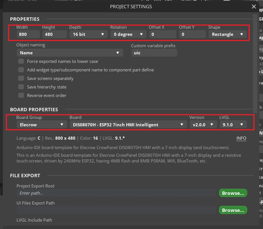
Open SquareLine Studio 1.6.1, click Create at the top to create a new project, select LVGL major version 9.1, and choose the vendor category Elecrow. In the template list, select DIS08070H - ESP32 7inch HMI Display 800x480 RGB - Arduino-IDE, which is tailored for the Elecrow CrowPanel 7-inch capacitive touchscreen, with preset parameters of 800×480 resolution and LVGL 9.1, then complete the project creation.
Note: This template is an Elecrow CrowPanel-specific Arduino project template that directly generates LVGL UI code matching the hardware; if you switch to a different screen model, you need to select the corresponding hardware template and verify the resolution and color depth settings.
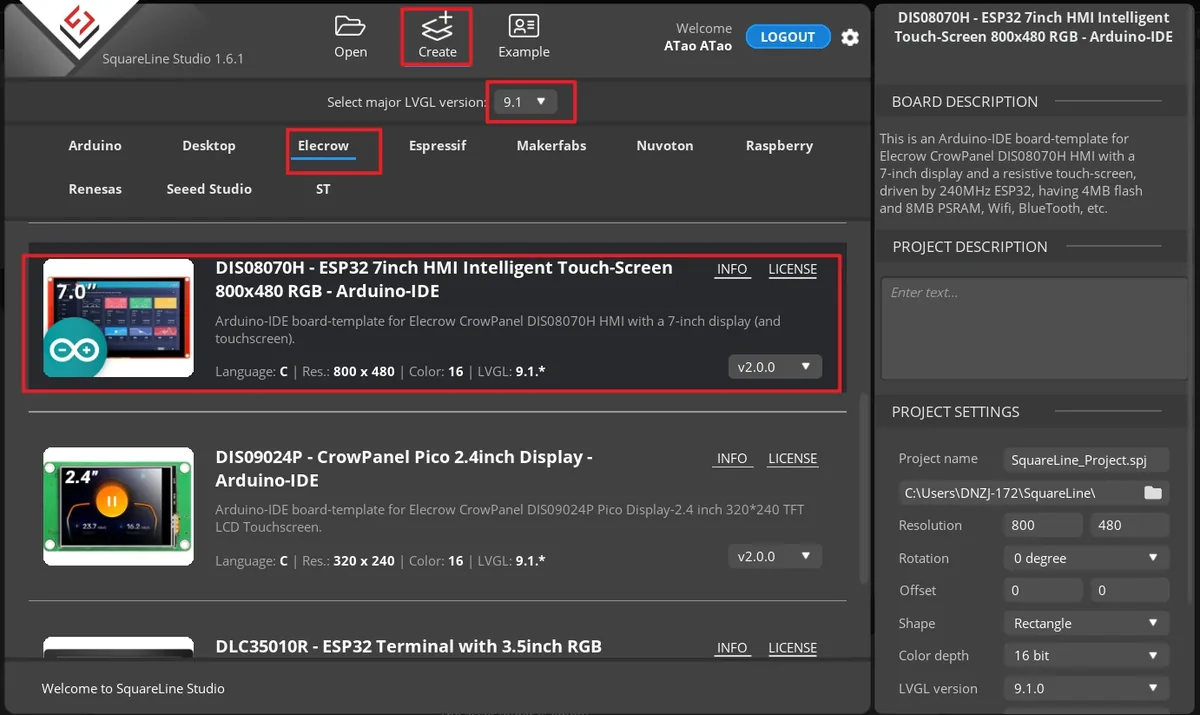
Enter the project name, set the LVGL version to 9.1.0, the resolution to width 800 and height 480, and the color depth to 16 bit, then click CREATE. After creation, the canvas should be landscape 800×480.
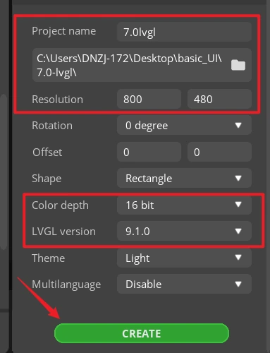
Note: A 16 bit color depth can represent 65,536 colors using an RGB 5:6:5 pixel format. Keep it consistent with the project's color configuration.
After the project opens, select Screen1 in the Screens panel on the left, and confirm that the central canvas is blank and the Inspector on the right shows the Screen properties. Subsequent widgets are all added to this page.
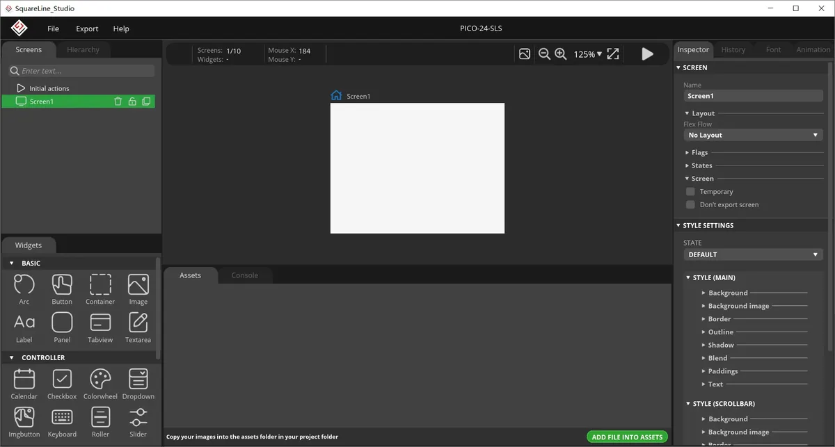
In the Assets area, click ADD FILE TO ASSETS and import LVGL-Assets-800x480/background.png, on.png, and off.png in turn. After importing, you should see three thumbnails.
Material link:
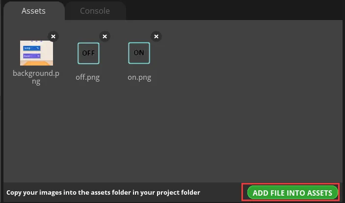
Note: Image assets support only the PNG format; the pixel size of an image should be smaller than the project screen size; a single image should not exceed 100 KB, and it is best to keep it within 30 KB to avoid affecting display smoothness.
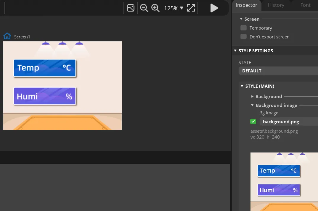
Select Screen1, expand STYLE SETTINGS > STYLE (MAIN) > Background on the right, and enable the background image setting.
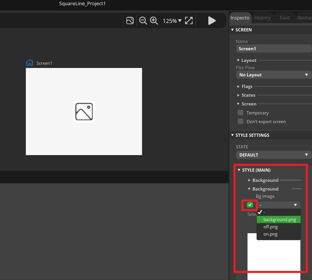
In Bg Image, select background. The canvas should immediately show the lesson background image, and the background should fully cover the entire page.
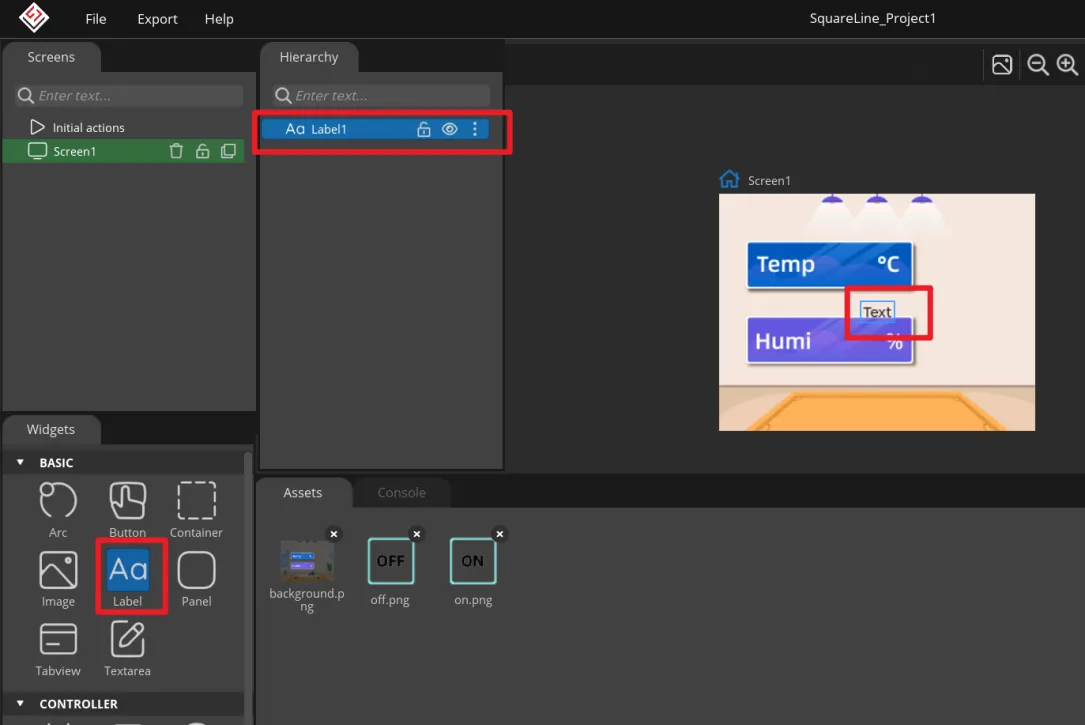
In the Widgets panel on the left, click Label to add a temperature label to Screen1. This label will be updated by the program with the temperature value.
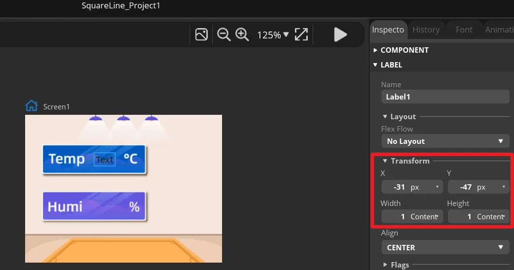
Select the temperature label, and in Transform adjust the X and Y position and the width and height so that it sits within the temperature display area of the background image. You can also drag it first, then fine-tune with the numeric values.
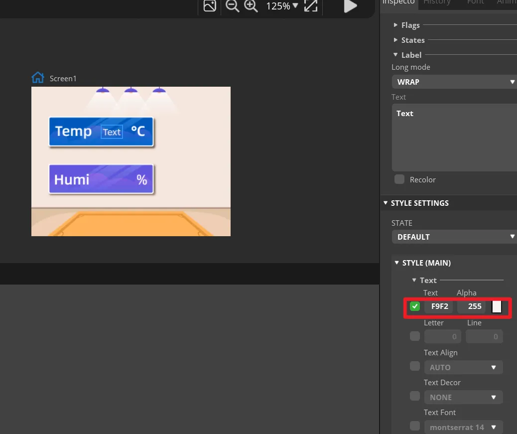
In the label's STYLE (MAIN), change the text color to white and set an appropriate font size. The text on the canvas should be clearly visible and not exceed the background frame.
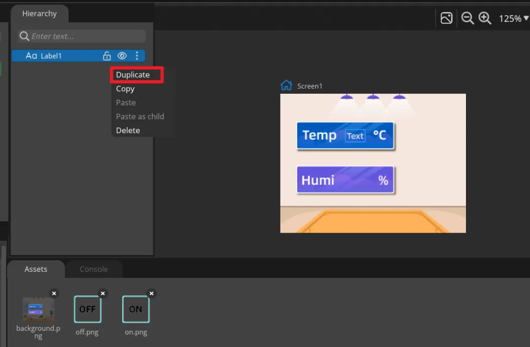
Right-click Label1 and select Duplicate to create Label2, then move it to the humidity display area. Keep the names Label1 and Label2, because the main program updates them by name.
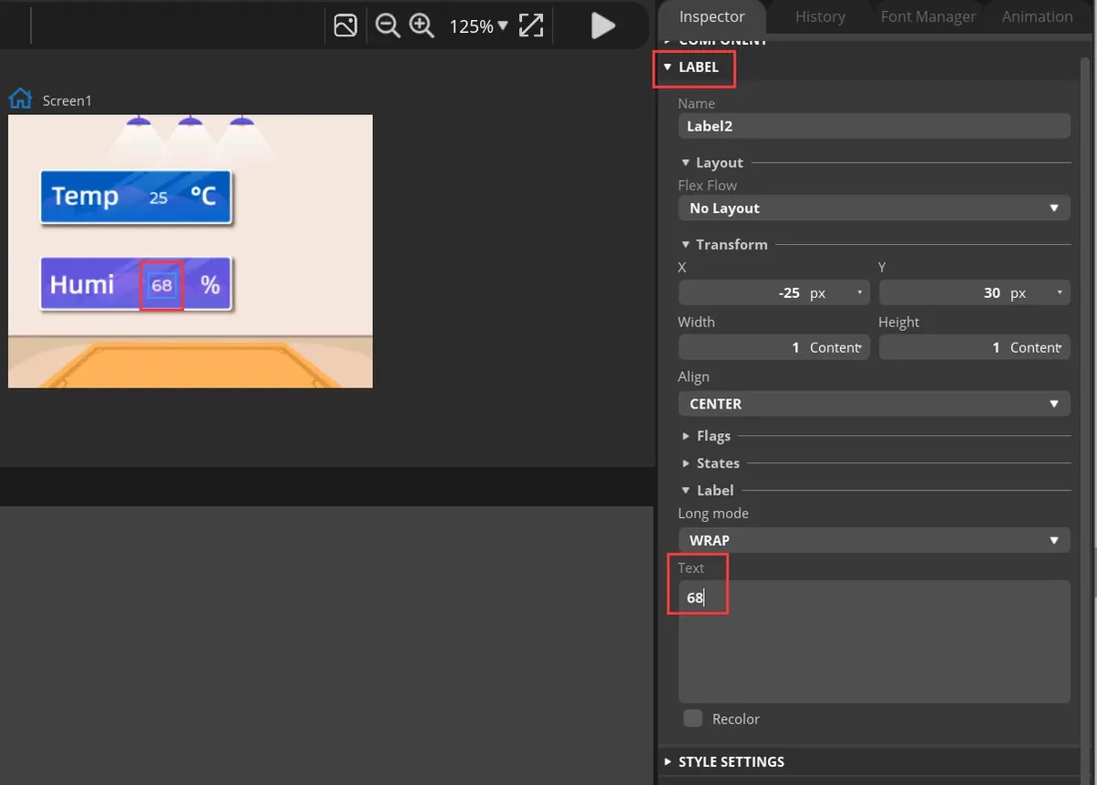
Select the two Labels respectively, and in Text enter default numbers that are convenient for preview. These are only design-time placeholder values; they will be replaced by DHT20 readings once the board runs.
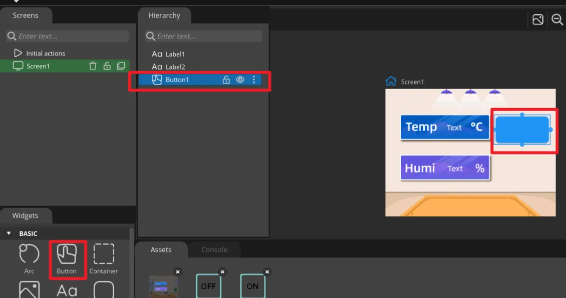
In Widgets, click Button to add the first button, and drag it to the ON area on the right side of the interface.
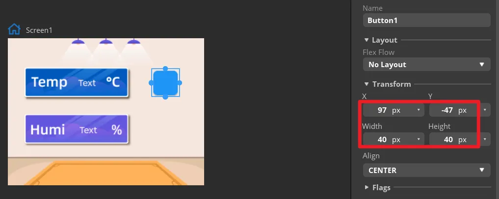
In Transform, set the size of the first button and adjust its position so that the button aligns with the ON area in the background.
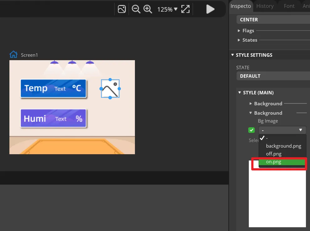
Expand the button's STYLE (MAIN) > Background, and select on.png as the background image. The ON icon should appear on the canvas.
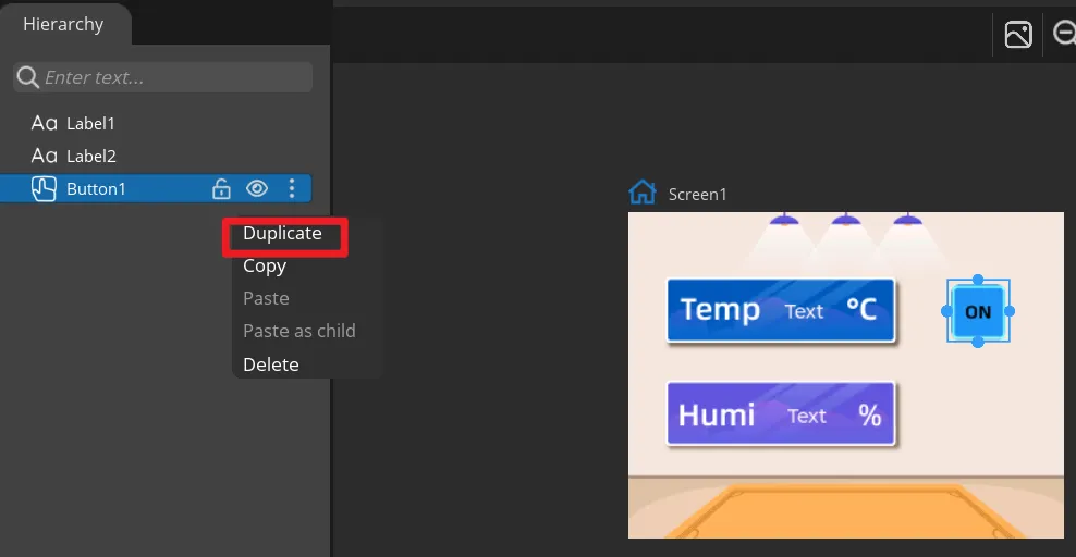
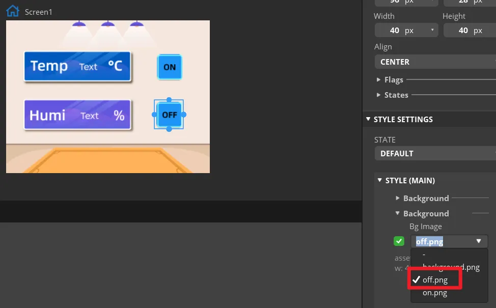
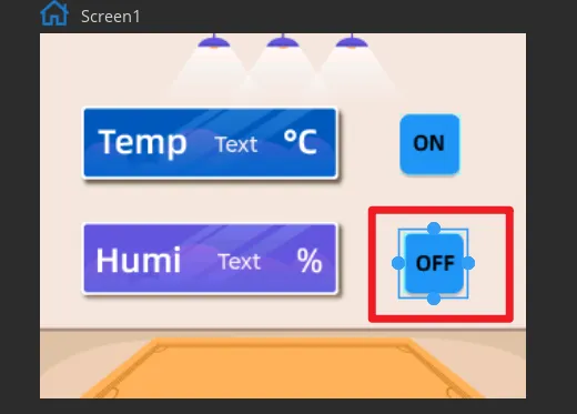
Duplicate Button1 to create Button2, move it to the OFF area, and change its background image to off.png. Keep the names Button1 and Button2 so they map to the exported event functions.
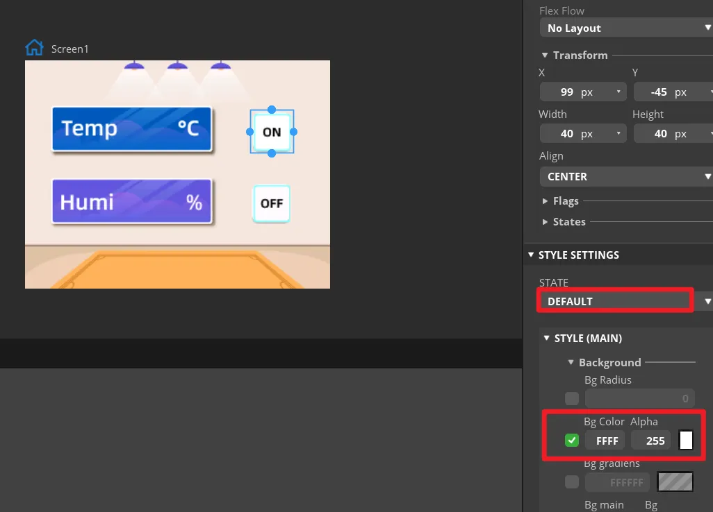
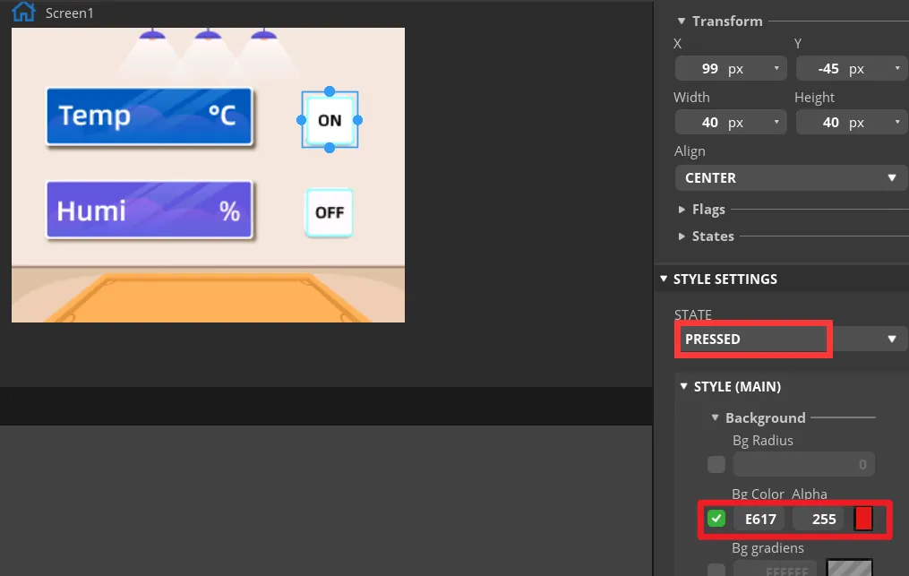
In the STATE settings of both buttons, check the DEFAULT and PRESSED states. The pressed state can use a distinct color change so that, in preview, you can tell whether a button is pressed. In Inspector -> Style Settings -> State, set the displayed background color to white, and set it to red when in the "fixed state". Apply the same parameters to the OFF button.
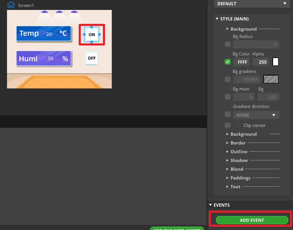
Select the ON button and click ADD EVENT.
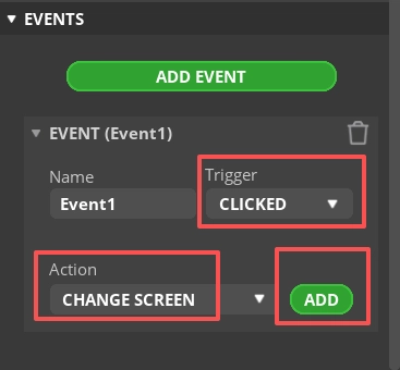
Select CLICKED as the trigger condition, and choose the trigger event in Action. This will be modified later in the generated program to implement GPIO38 output control.
Note: Since the button will ultimately control the LED on/off, you can add any event here first so that the exported UI file generates the button event code framework; the LED control code will be modified in a later step.
Complete this event. In the example, you can first select switching to the Screen1 screen to generate the event structure.
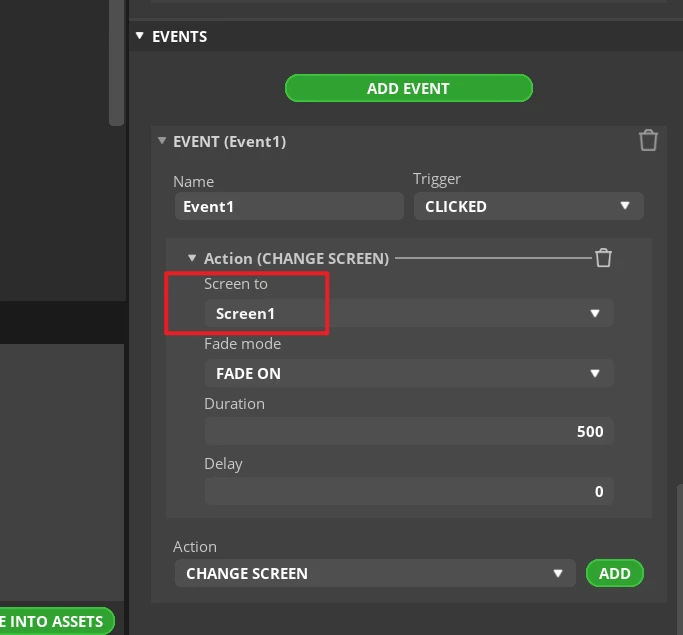
Add an event to the OFF button in the same way.
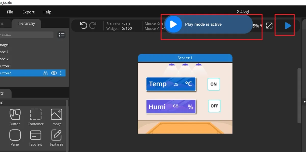
Click Run to preview the interface display and button states.
Open File > Project Settings, then configure the relevant settings for the exported files.

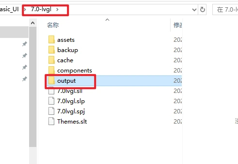
Set the export directory to an easy-to-find path containing only English characters, create a new output folder, confirm that the LVGL Include Path is lvgl.h, and then click APPLY CHANGES.
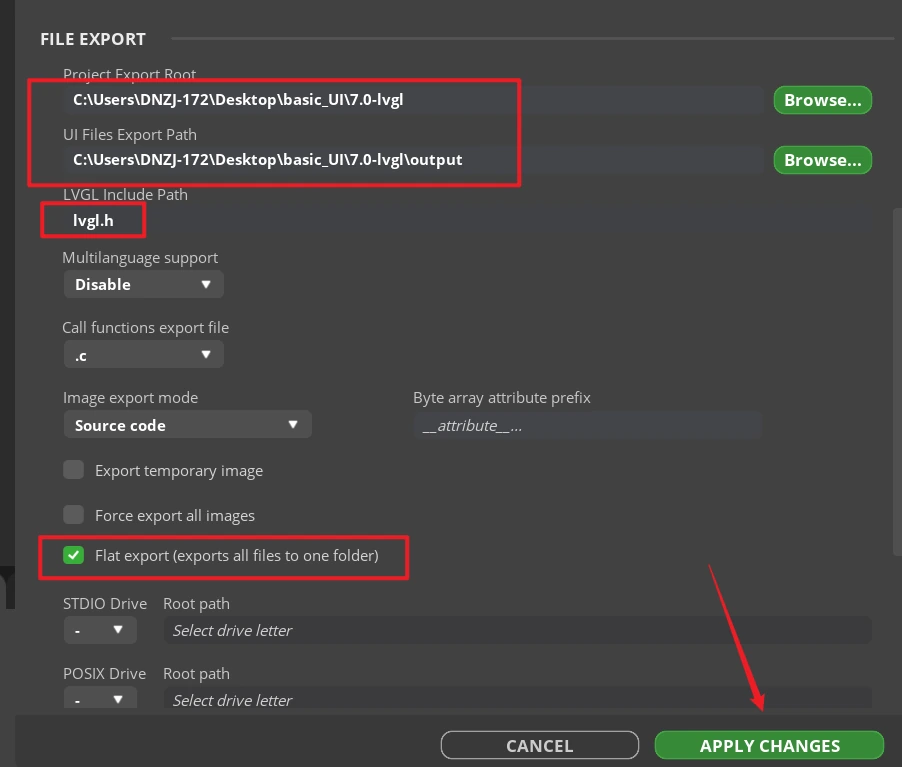
Tip: After selecting Flat export, all output files are placed in the same folder, so the program does not need to modify file paths. If Flat export is not selected, files are scattered across different folders and the compiler may fail to recognize them automatically, usually requiring manual path changes; therefore, it is recommended to keep it checked.
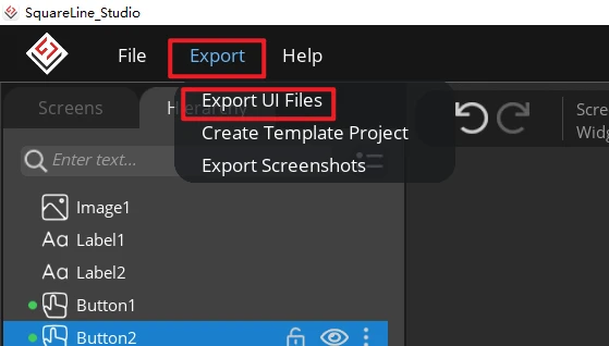
Click Export > Export UI Files. After export completes, the destination directory should contain ui.c, ui.h, ui_Screen1.c, the event files, helper files, and the image array files.
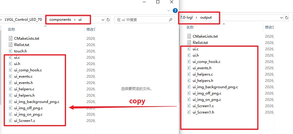
Copy all exported UI files (.c and .h) into the UI folder under Components of the project, and replace the files with the LVGL 9.1 version. In components/UI/CMakeLists.txt, make sure these files are included in the build.
8. Experimental Results
After power-on, the backlight turns on, and the screen displays the background image, the temperature/humidity values, and the ON/OFF buttons.
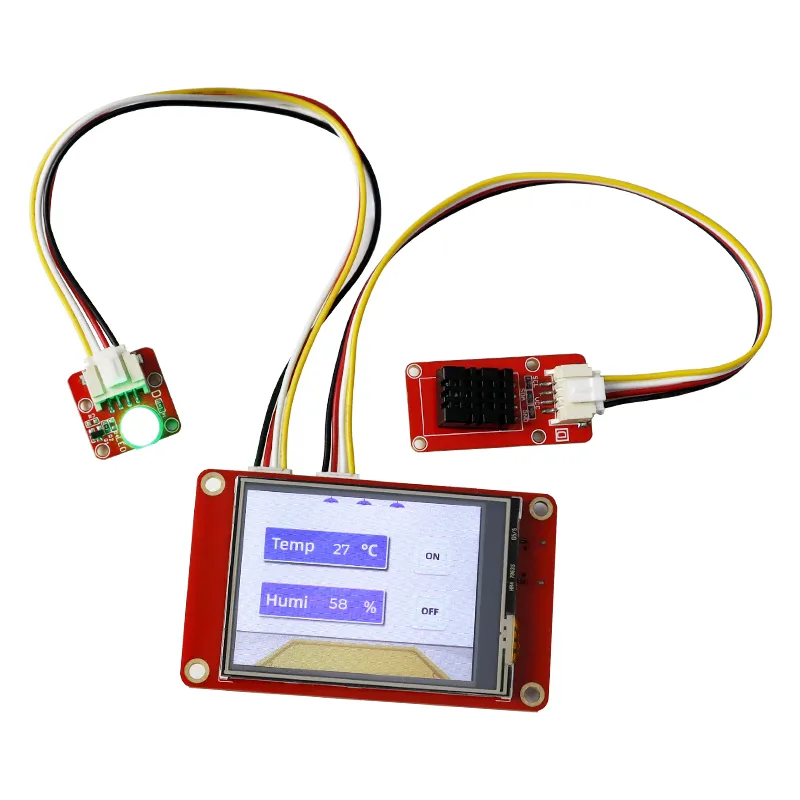
After clicking ON, the LED lights up.
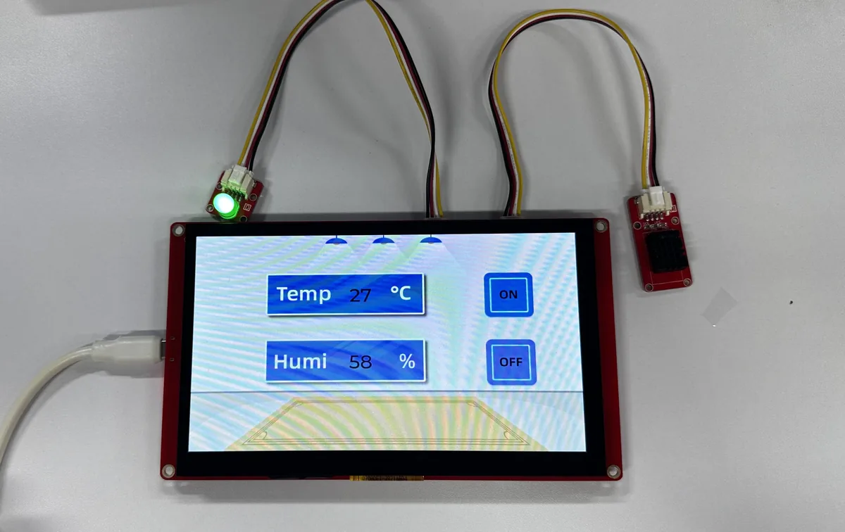
After clicking OFF, it turns off.