Display_Touch_LVGL: ESP-IDF 5.5.4 Driving a 4.3-inch HMI Display with LVGL 9.1
1. Course Introduction
This lesson uses ESP-IDF 5.5.4 with espressif/arduino-esp32 3.3.8 as a project component to drive an ESP32-S3 4.3-inch, 480 × 272 HMI display. Arduino GFX drives the NV3047 RGB LCD, XPT2046 provides touch input over SPI, LVGL 9.1.0 refreshes the screen using a partial drawing buffer in external PSRAM, and the SquareLine_Project exported from SquareLine Studio 1.6.1 supplies the background along with the ON and OFF image buttons.
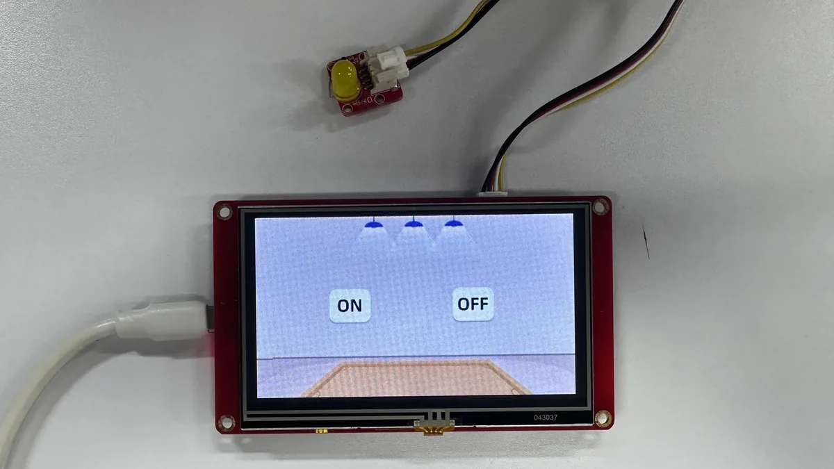
After flashing the firmware, the serial port prints app_main start and the LCD initialization result, the backlight turns on, and the UI appears. Tapping the ON button lights the GPIO 38 indicator, while tapping the OFF button turns it off. The IDF version does not print touch coordinates; the acceptance check focuses on whether the UI is stable, the buttons respond accurately, and GPIO 38 toggles accordingly.
Reference materials:
2. Learning Objectives
- Identify the Arduino-as-component project structure and the
app_main()entry point within ESP-IDF 5.5.4. - Explain the call relationships among the RGB LCD, XPT2046, LVGL callbacks, the PSRAM buffer, and the SquareLine UI.
- Configure ESP32-S3, 4 MB Flash, custom partitions, and QSPI PSRAM using the provided
sdkconfig. - Build, flash, and monitor the project, and locate display initialization or memory allocation errors from the logs.
- Determine whether the display, touch, and event chains are working by checking the linkage between the UI buttons and the GPIO 38 indicator.
3. What You Will Need
- One ESP32-S3 4.3-inch HMI development board with a 480 × 272 LCD and an XPT2046 touch controller.
- One USB data cable that supports data transfer.
- One LED module connected to GPIO38.
- VS Code, the ESP-IDF extension, and ESP-IDF 5.5.4.
- VS Code + ESP-IDF Extension: Click here for the installation tutorial.
- The complete
LVGL_IDFproject, includingmain,components/UI,components/lvgl-3,components/Arduino_GFX-master,components/XPT2046_Touchscreen, andmanaged_components. - The project pins
espressif/arduino-esp32to 3.3.8; do not updatedependencies.lockbefore building. - SquareLine Studio 1.6.1; UI project parameters: LVGL 9.1.0, 480 × 272, project name
SquareLine_Project. - A temporary project path containing only ASCII characters, for example
C:/Espressif/projects/LVGL_IDF. The current ESP-IDF toolchain may fail when generating Kconfig files in absolute paths that contain Chinese characters.
4. Software Operation Steps
The steps below are performed primarily using the Espressif IDF extension for VS Code. On first use, complete them in order; do not flash until the target chip and serial port have been set.
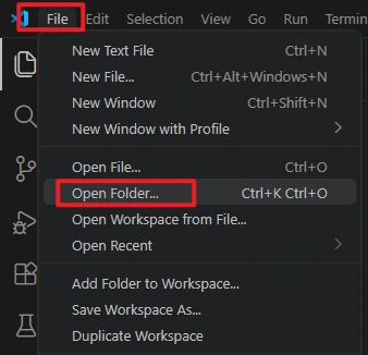
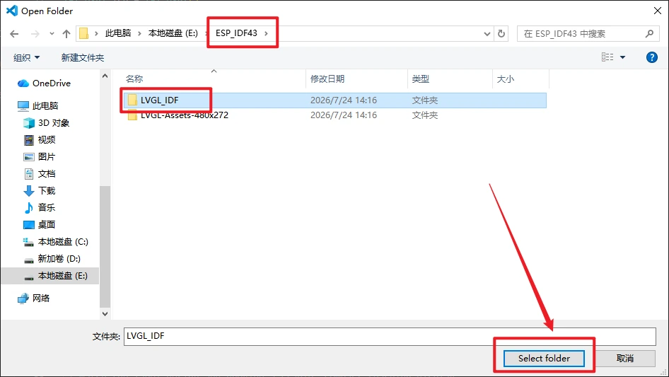
In VS Code, select File > Open Folder to open the project folder.
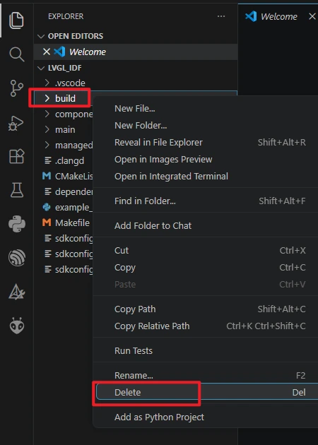
Run the Build -> Delete command to completely clear the build cache and path files left behind by the old project, avoiding compilation conflicts.
Verify that ESP-IDF 5.5.4 is installed.

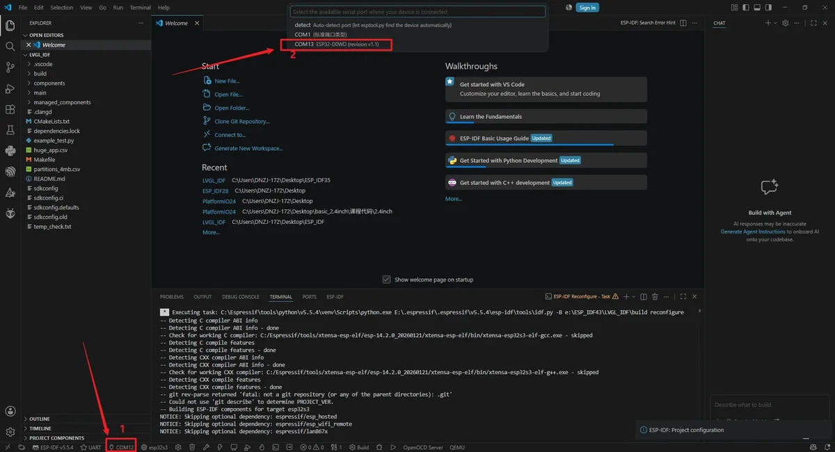
Connect the board with the USB data cable, click the port name in the status bar, and select the COM port that the board actually appears on. The port number varies by computer; if unsure, unplug the board and observe which port disappears from the list.
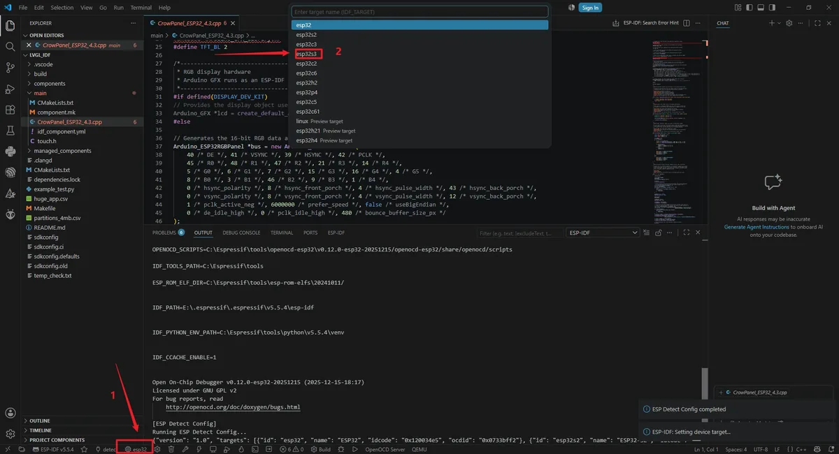
Click the chip icon in the VS Code status bar, run ESP-IDF: Set Espressif Device Target, and select esp32s3 to set the target chip.
For the OpenOCD configuration, select ESP32-S3 chip (via builtin USB-JTAG) to prevent the plugin from repeatedly prompting that the configuration is missing.

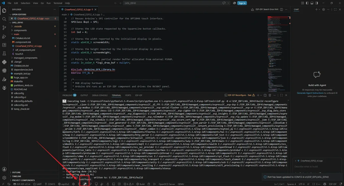
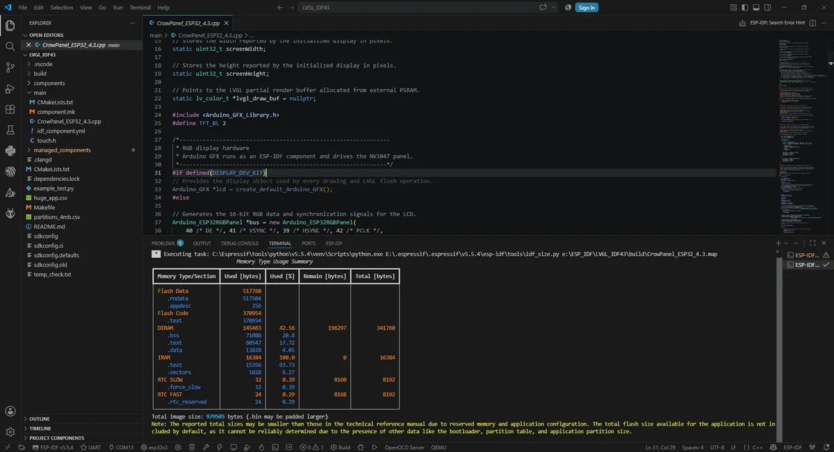
Click the Build (wrench) button in the status bar, or run idf.py build in the terminal. The first build takes a long time; the bottom-right corner should then show that the project build is complete.

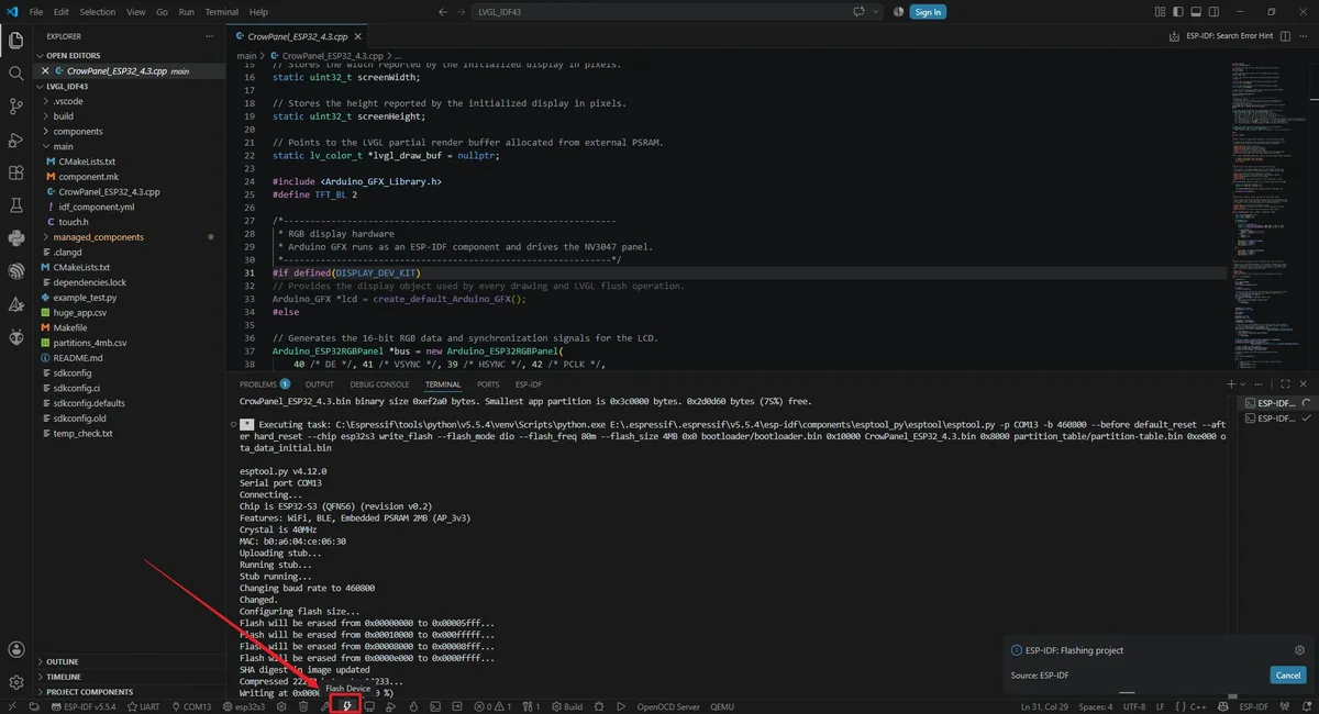
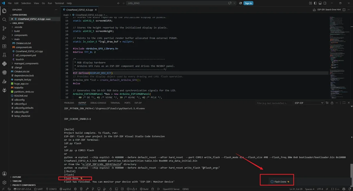
Confirm that the flash method in the status bar is UART, then click the lightning-shaped Flash button; you can also run idf.py -p COMx flash, replacing COMx with the actual port. The board resets automatically after writing finishes.
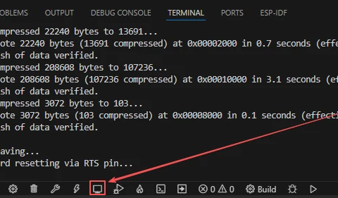
After uploading the code, click the Monitor button to open the serial port monitor; the baud rate is set to 115200 by default. After the monitor is opened, it should first display the ESP-IDF startup information, and then continuously print the serial port printing information set in your code.
5. Hardware Operation Steps
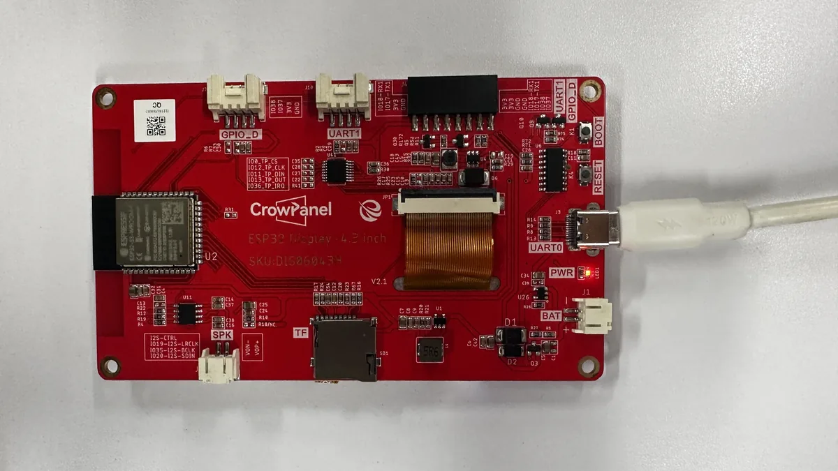
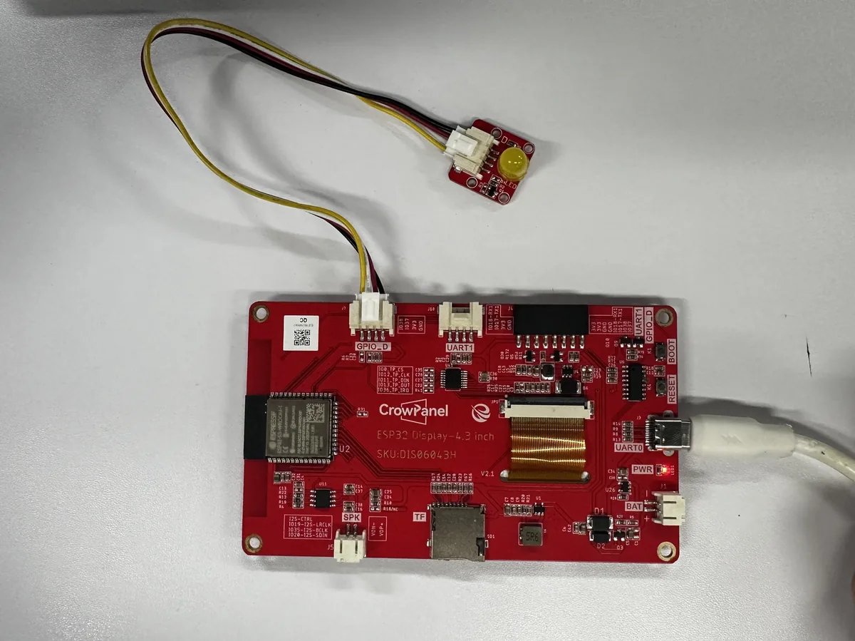
Keep the board powered off and verify that the LCD and touch cables are secured. If using an external LED, connect it to the connector labeled GPIO_D, whose signal line corresponds to GPIO 38; after confirming orientation and power pins, connect the board to the computer with a USB-C cable that supports data transfer.
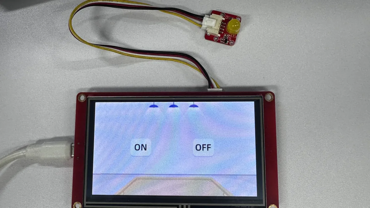
After flashing, press the reset button. The LCD backlight should turn on, and the screen should fully display the background and the two image buttons, ON and OFF; there must be no garbage display, misalignment, white blocks, or missing areas.
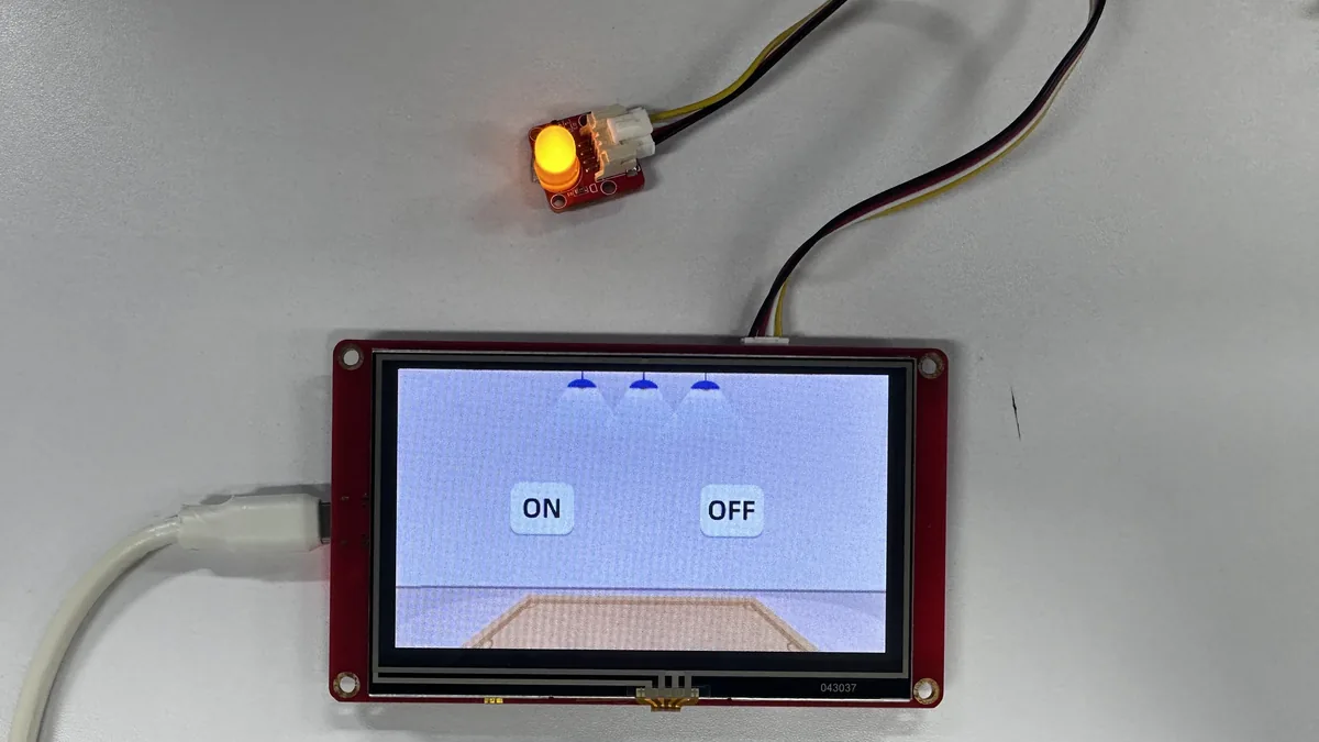
Tap the ON image button with a finger; do not use sharp or conductive objects. The GPIO 38 LED should light up.
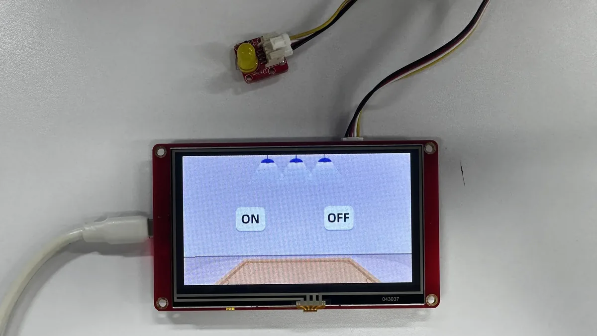
Tap the OFF image button; the GPIO 38 LED should turn off.
6. Key Code Explanation
6.1 Initializing the Arduino Runtime in ESP-IDF
// ESP-IDF expects a C-linkage application entry point.
extern "C" void app_main()
{
    // Start Arduino-as-component before using Serial, millis, or GPIO APIs.
    initArduino();
    // Initialize serial diagnostics and the LVGL core/tick source.
    Serial.begin(115200);
    lv_init();
    lv_tick_set_cb(millis);
}
ESP-IDF calls app_main() with C linkage, and the project then uses Arduino's Serial, millis(), pinMode(), and Arduino GFX, so initArduino() must be called first. If this call is removed, some of the underlying Arduino API services are not yet ready, and the program may malfunction during initialization or peripheral access.
6.2 RGB Display Timing
/* RGB panel control/data pins and timing values are board-specific. */
Arduino_ESP32RGBPanel *bus = new Arduino_ESP32RGBPanel(
    // DE, VSYNC, HSYNC, and PCLK control pins.
    40, 41, 39, 42,
    // RGB565 red, green, and blue data pins.
    45, 48, 47, 21, 14,
    5, 6, 7, 15, 16, 4,
    8, 3, 46, 9, 1,
    // Horizontal and vertical synchronization timing.
    0, 8, 4, 43,
    0, 8, 4, 12,
    // Pixel clock polarity, speed, and byte order.
    1, 6000000, false,
    0, 0, 480
);
The IDF project uses a 6 MHz pixel clock with the corresponding horizontal and vertical blanking parameters. After correct execution, lcd->begin() returns true, and a stable image appears once the backlight turns on. Incorrect pins or timing can cause a black screen, garbage display, color shift, or an unstable image; when troubleshooting, first restore the lesson's parameters.
6.3 Touch Calibration, Boundary Limiting, and Filtering
// Map raw XPT2046 ADC values into the visible 480 x 272 screen range.
int16_t x = clamp_touch_coord(map(p.x, 4000, 200, 0, 479), 0, 479);
int16_t y = clamp_touch_coord(map(p.y, 200, 3600, 0, 271), 0, 271);

// While pressed, retain three quarters of the previous stable coordinate.
if (last_pressed) {
    stable_x = (stable_x * 3 + x) / 4;
    stable_y = (stable_y * 3 + y) / 4;
} else {
    stable_x = x;
    stable_y = y;
}
map() converts the raw XPT2046 values into 480 × 272 pixel coordinates, and clamp_touch_coord() prevents noise from producing negative or out-of-range coordinates. While pressed, the old coordinate carries three-quarters weight and the new coordinate one-quarter weight, reducing jitter; over-strong filtering makes button response feel sluggish, so the old-value weight should not be increased arbitrarily.
6.4 Allocating the LVGL Drawing Buffer from PSRAM
// Allocate the 40-line RGB565 buffer from external PSRAM with byte access.
const size_t draw_buf_pixels = screenWidth * 40;
lvgl_draw_buf = (lv_color_t *)heap_caps_malloc(
    draw_buf_pixels * sizeof(lv_color_t),
    MALLOC_CAP_SPIRAM | MALLOC_CAP_8BIT);
The buffer holds 40 rows of RGB565 pixels, about 38.4 KB at a width of 480 pixels. Using MALLOC_CAP_SPIRAM places the large block in external PSRAM, and MALLOC_CAP_8BIT guarantees byte-wise access. If allocation fails, the program prints draw buffer alloc failed and halts; first check the PSRAM configuration and the hardware soldering.
6.5 Registering LVGL Callbacks and Creating the UI
// Connect LVGL's display output to the physical LCD flush callback.
lv_display_set_flush_cb(disp, my_disp_flush);
lv_display_set_buffers(disp, lvgl_draw_buf, NULL,
                       draw_buf_pixels * sizeof(lv_color_t),
                       LV_DISPLAY_RENDER_MODE_PARTIAL);

// Register the touch reader as an LVGL pointer device.
lv_indev_set_type(indev, LV_INDEV_TYPE_POINTER);
lv_indev_set_read_cb(indev, my_touchpad_read);
// Create the background, buttons, and events exported by SquareLine Studio.
ui_init();
The display callback, drawing buffer, and touch callback must be registered before creating the SquareLine UI. If the display callback is wrong, LVGL may run but the LCD will not update; if the touch callback is wrong, the UI displays normally but the buttons do not respond; if ui_init() is not called, the background and buttons are not created.
6.6 UI State Driving GPIO 38
while (1)
{
    // Apply the state selected by the on-screen buttons to GPIO 38.
    if (led == 1) {
        digitalWrite(38, HIGH);
    } else {
        digitalWrite(38, LOW);
    }

    // Service LVGL timers so drawing and touch processing continue.
    lv_timer_handler();
    delay(5);
}
The SquareLine button callback modifies led, and the main task loop writes the state to GPIO 38 and services LVGL every 5 ms. If the loop spends a long time on other blocking operations, touch and screen refresh slow down; if lv_timer_handler() is removed, the display may stay on the initial screen and buttons stop being processed.
7. UI Asset Creation and Integration
This section uses SquareLine Studio 1.6.1 to demonstrate the UI creation process again. The lesson already provides the exported UI files, so beginners can read this section to understand the flow and then use the project files directly to build. When creating a new project, you must select LVGL 9.1.0;
How to download SquareLine Studio: https://www.elecrow.com/wiki/Create_LVGL_UI_with_SquareLine_Studio.html.
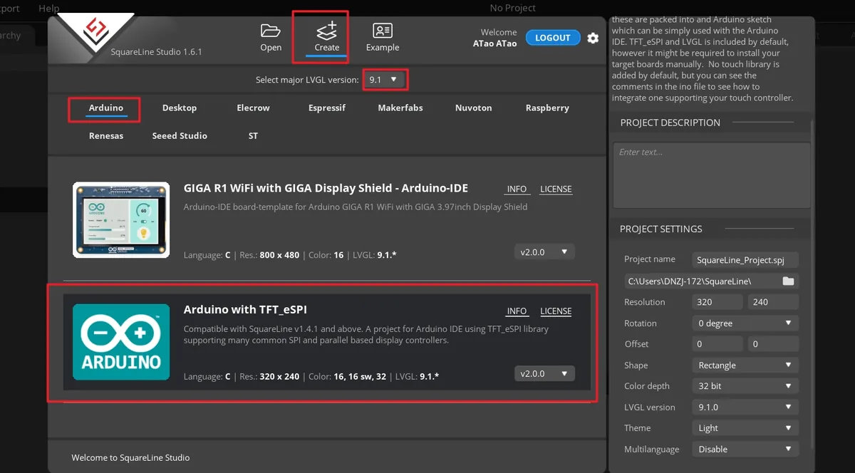
Launch SquareLine Studio 1.6.1, click Create, and select the Arduino with TFT_eSPI template for the Arduino platform. This template generates the UI file framework suited to Arduino and TFT_eSPI projects.
Note: When the Arduino framework is selected, SquareLine Studio shows only Arduino with TFT_eSPI. It generates template code for TFT_eSPI, but SquareLine Studio also supports other graphics libraries; when switching to other hardware, you must modify the display code according to the actual library.
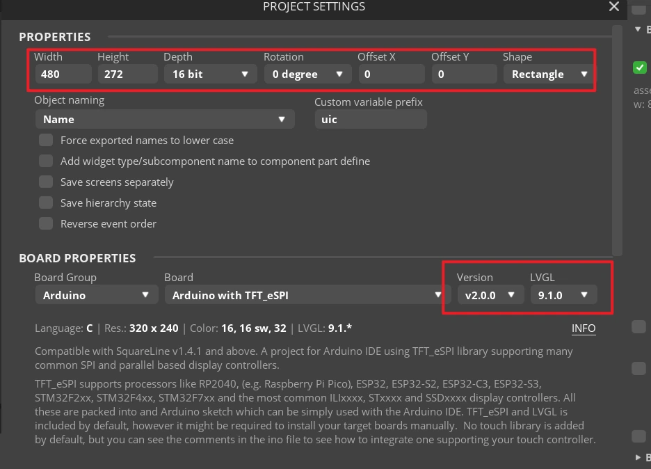
Enter the project name SquareLine_Project, set the resolution to width 480 and height 272, set the color depth to 16 bit, set the LVGL version to 9.1.0, then click CREATE.
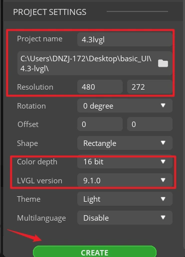
Note: 16 bit color depth can represent 65,536 colors, using the RGB 5:6:5 pixel representation. Keep it consistent with the project's color configuration.
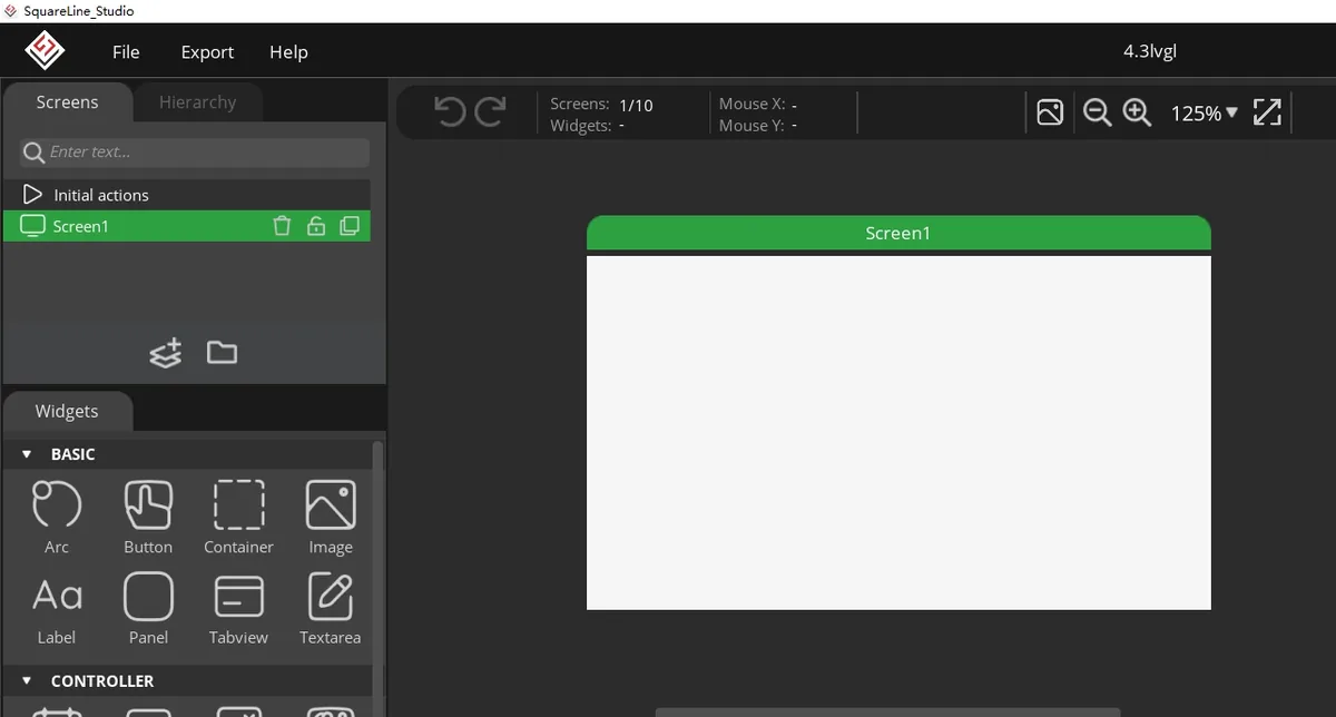
After the project opens, select Screen1 in Screens on the left.
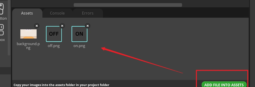
In the Assets area, click ADD FILE TO ASSETS and import the provided background.png, on.png, and off.png. After import, three thumbnails should appear.
Material link:
Select Screen1, expand STYLE SETTINGS > STYLE (MAIN) > Background on the right, and enable the background image setting. 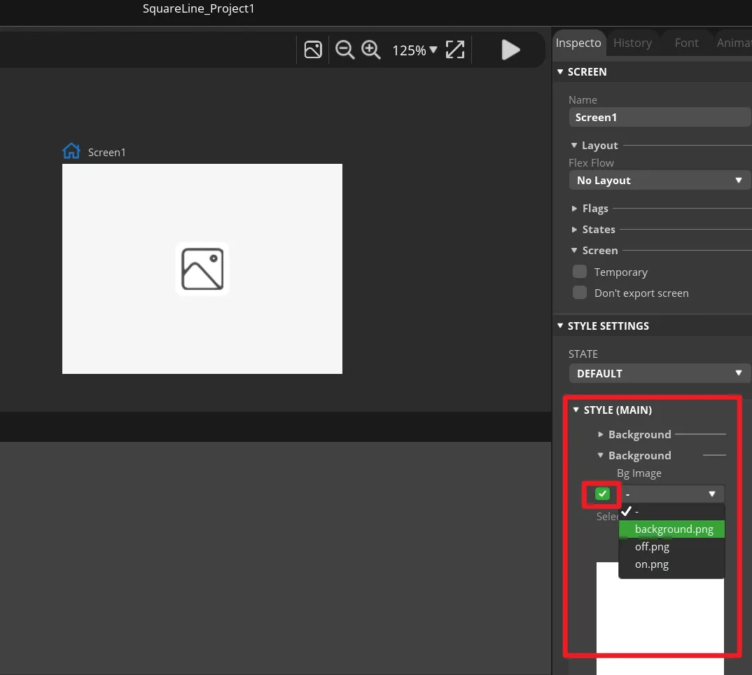
In Bg Image, select background and disable unneeded page scrolling. The background should fully cover the 480 × 272 canvas. 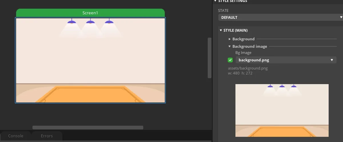
In Widgets on the left, click Button to add Button1 to Screen1, then move the button to the ON area on the left side of the screen. 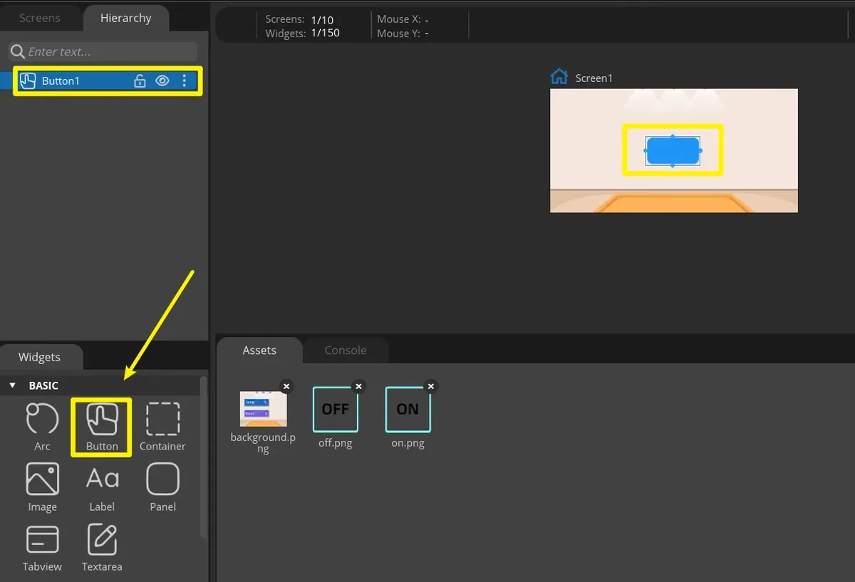
Select Button1 and set its position and size in Transform. 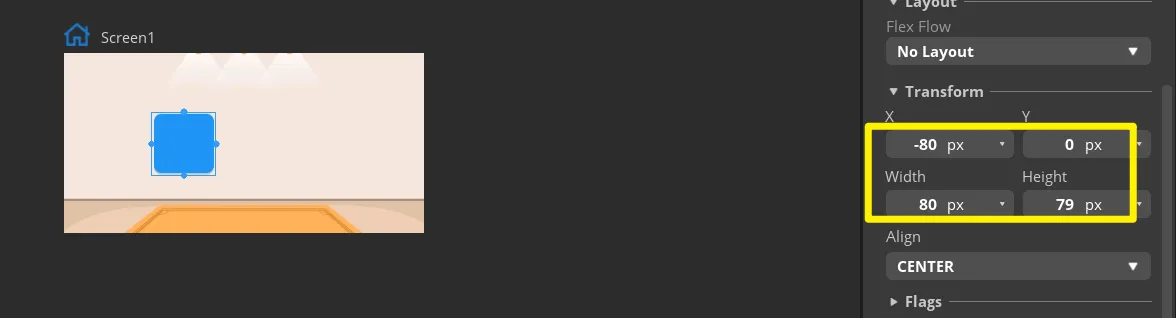
Expand Button1's STYLE (MAIN) > Background and select on.png. The ON icon should appear on the canvas without stretching or cropping. 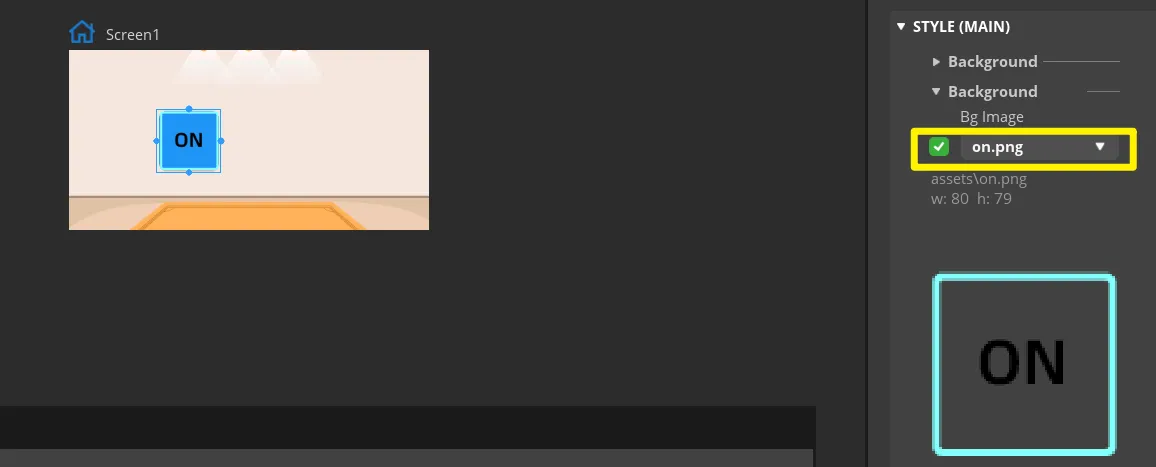
Duplicate Button1 to get Button2 and move it to the OFF area on the right. Duplicating preserves the same size and base style. 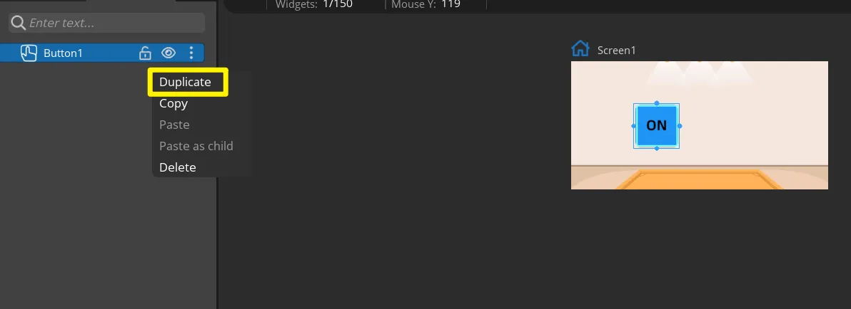
In Button2's background setting, select off.png and confirm that the ON and OFF images are on the left and right sides of the screen respectively. 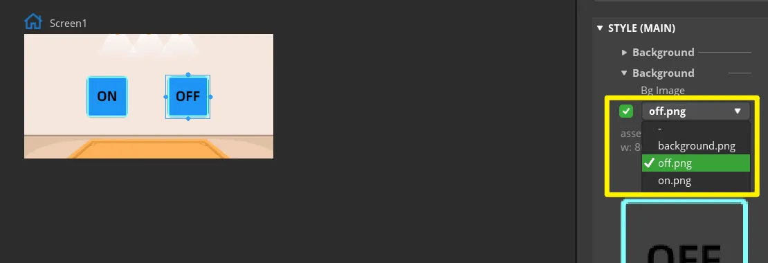
Select the button, check the DEFAULT state in STATE, and set the displayed background color to white. 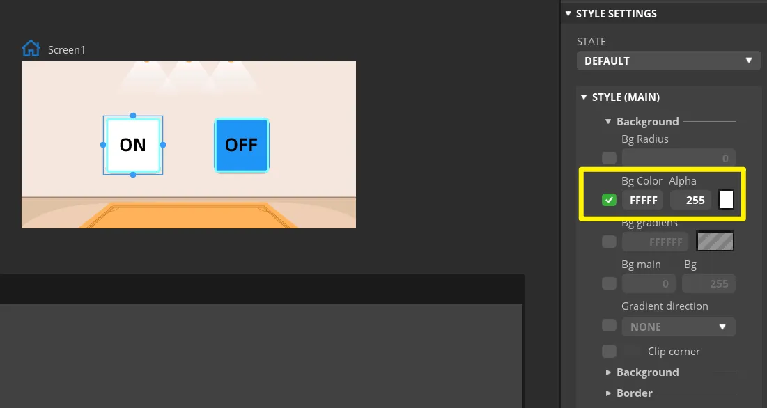
Switch to the PRESSED state, set a recognizable press feedback, and set the displayed background color to red. 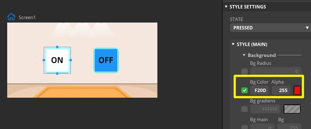
Set the same parameters for the "off" button.
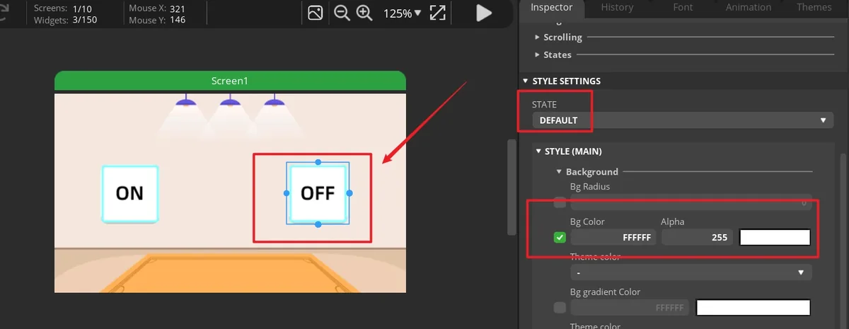
Note: Because the buttons can control the on/off state of the LED, we can add any events here to handle button events. When the UI files are exported, these events are used as code scaffolding. Later, we will modify the button event code to control the LED on/off state.
Select Button1, open the EVENTS panel and click ADD EVENT to create the first button event. 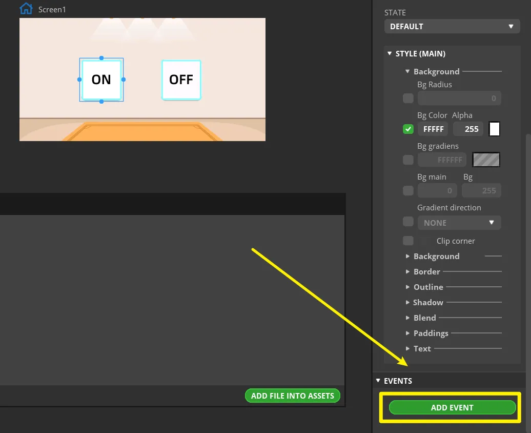
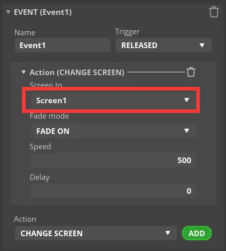
Select "CLICKED" as the trigger condition, and choose the trigger event in "Action". The generated program will later be modified to implement the LED control function.
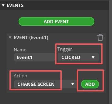
Caution: Since the buttons will ultimately control the LED on and off, you can add any event here for now to let the exported UI file generate the button event code framework; the LED control code will be modified in a later step.
Complete this event. Here, I choose to switch screens, that is, switch to the Screen1 screen.
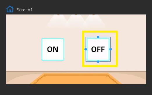
Add an event for Button2 using the same method. The two buttons must generate different event functions, into which the on and off states will be written separately later.
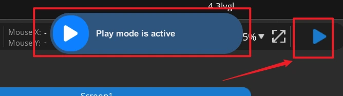
Click Run.
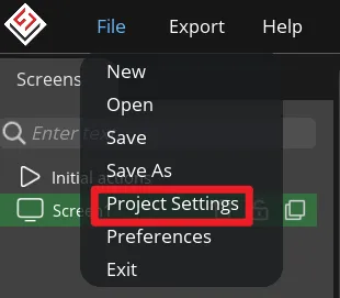
Open File > Project Settings, then configure the relevant settings for the exported files.
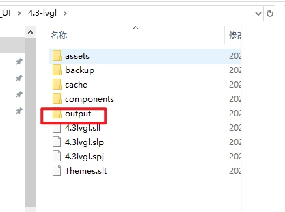
Set the export directory to an easily accessible path consisting of English characters only, create a new output folder, fill in and confirm that the LVGL Include Path is lvgl.h, then click APPLY CHANGES after confirmation.
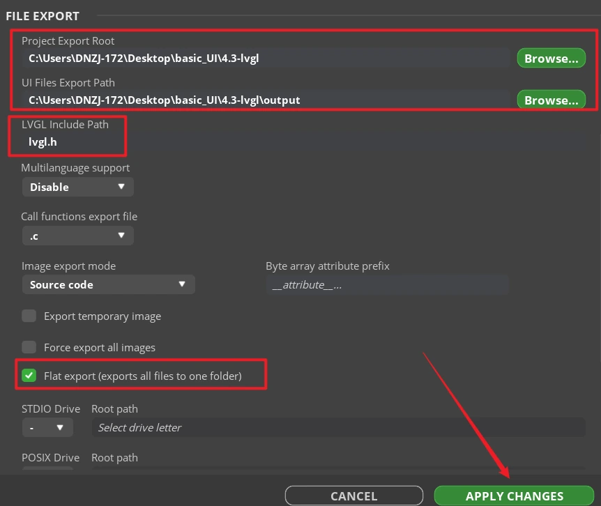
Tip: After selecting Flat export, all output files will be placed in the same folder, and the program will not need to modify file paths anymore. If Flat export is not selected, files will be scattered across different folders, and the compiler may fail to recognize them automatically, usually requiring manual path changes; therefore, it is recommended to keep it checked.
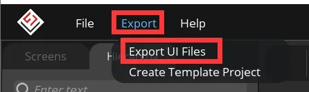
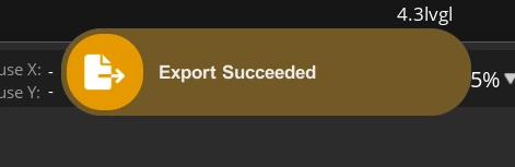
Click Export > Export UI Files. Wait for the export to complete. Once the export is finished, ui.c, ui.h, ui_Screen1.c, the event files, helper files, and image array files should appear in the target directory.
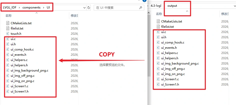
Copy all exported UI files (the .c and .h files) into the UI folder under the project's Components directory, replacing them with the LVGL 9.1 version. Make sure components/UI/CMakeLists.txt includes all these files in the compilation.
8. Observed Behavior
After the program resets, the serial port first outputs startup information, then the LCD backlight turns on and display initialization is completed. Once running stably, the screen shows the full background and the two image buttons. While a finger is pressed on the screen, the serial port continuously outputs the mapped x and y coordinates; clicking the left ON button lights the GPIO 38 indicator, and clicking the right OFF button turns the indicator off.
ON -> LED on.
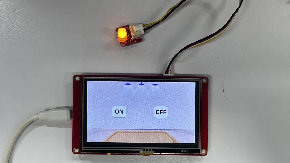
OFF -> LED off.