LVGL_IDF_2.4: Touch UI, Temperature/Humidity Display, and LED Control under ESP-IDF 5.5.4
1. Course Introduction
In this lesson, we use ESP-IDF 5.5.4 to build a 2.4-inch ESP32 touchscreen application, and reuse APIs such as TFT_eSPI, Wire, Serial, and millis() through the Arduino-ESP32 3.3.8 component. The program initializes the ILI9341 LCD, touch, DHT20, LVGL 9.1.0, and the UI exported from SquareLine Studio 1.6.1 in app_main(), then runs a FreeRTOS task loop to continuously process the UI, update temperature and humidity every second, and control GPIO25 based on the ON/OFF button.
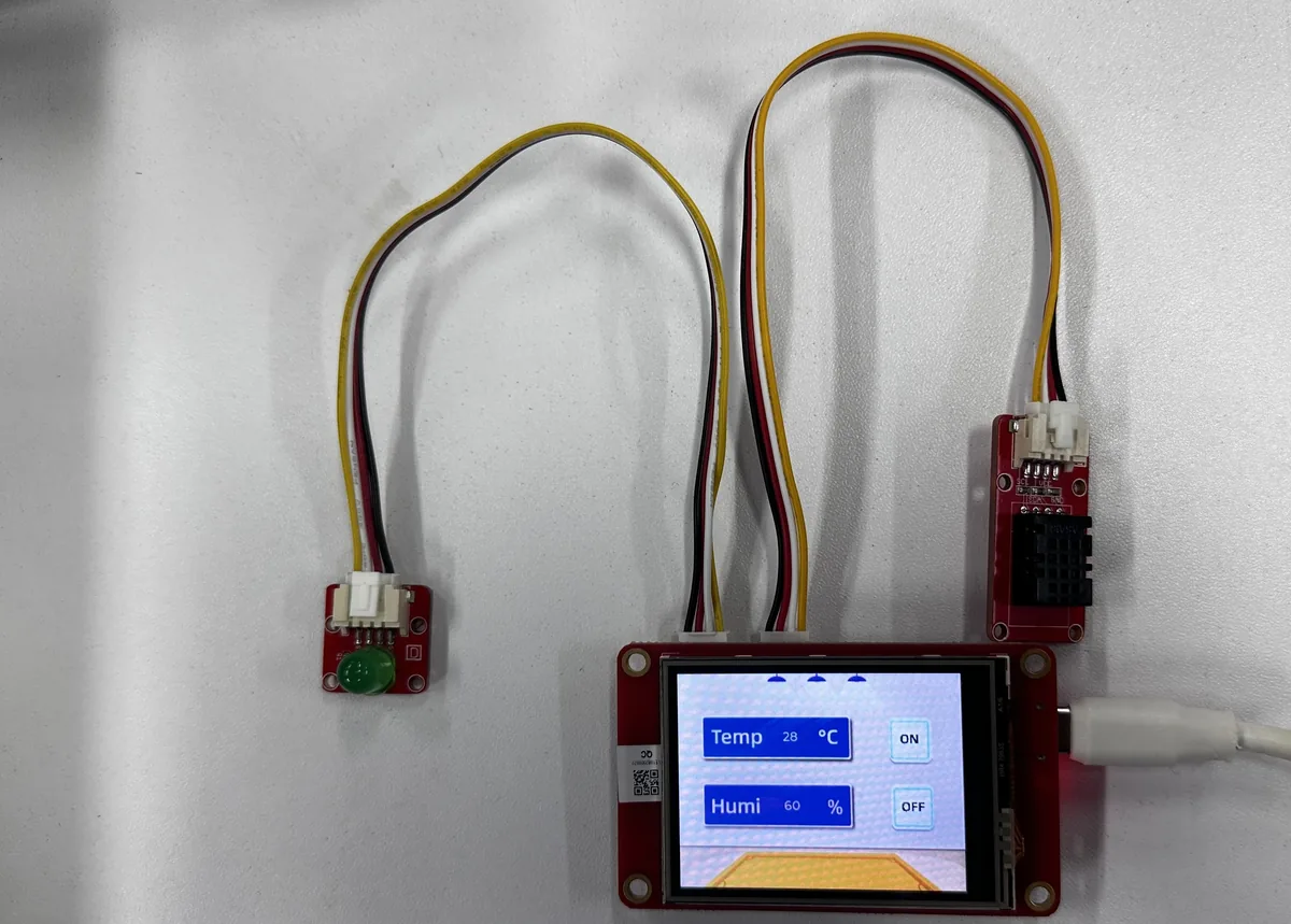
After the firmware is flashed, the LCD displays a background, two sensor values, and two image buttons. When the learner taps a button, the UI's C event code modifies the shared variable led, and the C++ main program immediately updates the LED output. Touch coordinates are mirrored along the X-axis in landscape orientation so that the tap location aligns with the UI. This lesson verifies the complete chain from ESP-IDF component management, LCD refresh, touch reading, to UI events and hardware output.
References:
2. Learning Objectives
- Be able to reconfigure, build, flash, and monitor a project for the
esp32target using ESP-IDF 5.5.4. - Be able to explain the relationship between ESP-IDF
app_main(), the Arduino compatibility layer, and the FreeRTOS task loop. - Be able to explain the execution order of LVGL partial refresh, touch coordinate mirroring, and SquareLine UI initialization.
- Be able to verify that the DHT20 updates the label every 1 second and to control GPIO25 through touch buttons.
- Be able to locate common faults based on build logs, backlight, UI, touch, and sensor behavior.
3. What You Need to Prepare
- One 2.4-inch ESP32 touchscreen development board, targeting the classic
esp32. - One USB data cable that supports both power delivery and data transfer.
- One DHT20 temperature and humidity module, connected to GPIO22 (SDA) and GPIO21 (SCL).
- One LED module, connected to GPIO25.
- VS Code, the Espressif IDF extension, and ESP-IDF 5.5.4, or an ESP-IDF 5.5.4 terminal where
export.ps1has been run. - VS Code + ESP-IDF Extension: Click here for the installation tutorial
- The complete project
ESP_IDF/LVGL_IDF. - The Windows build path must contain only ASCII characters. Before starting the lab, copy
LVGL_IDFentirely to a pure-English path, for exampleC:/esp_projects/LVGL_IDF/; do not build directly inside the course-material path that contains Chinese characters. - The first configuration requires network access to download or verify managed components. Even when
managed_components/already exists, the dependency lock file remains authoritative.
4. Software Operation Steps
The following steps are performed primarily using the Espressif IDF extension in VS Code. On first use, complete them in order; do not flash directly before the target chip or serial port has been set.
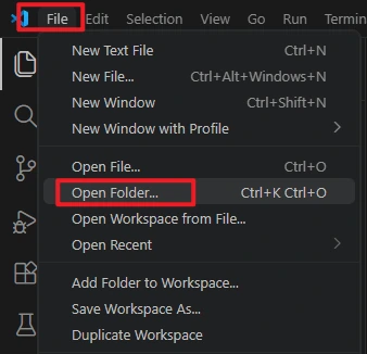
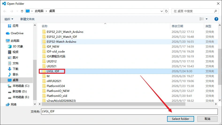
In VS Code, select File > Open Folder to open the project.
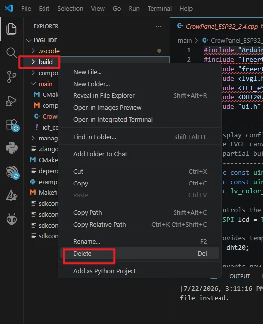
Run the Build -> Delete command to completely clear the build cache and path files left over from the old project, avoiding compilation conflicts.
Make sure ESP-IDF 5.5.4 is installed.

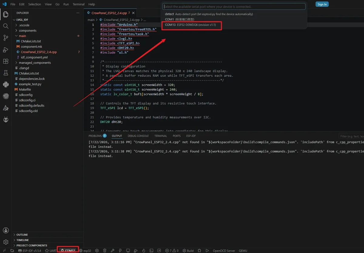
Connect the development board with a USB data cable, click the port name in the status bar, and select the COM port where the board actually appears. The port number varies by computer; if unsure, unplug the board and observe which port disappears from the list.
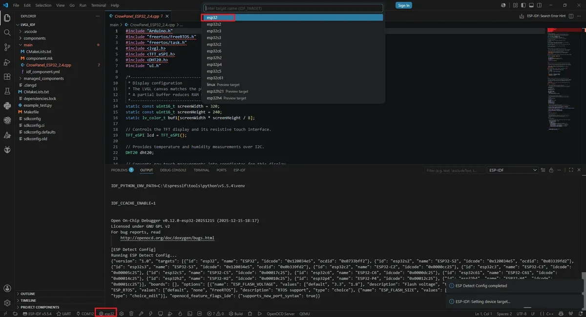
Click the target chip name in the status bar, or run ESP-IDF: Set Espressif Device Target, and select esp32 from the list.
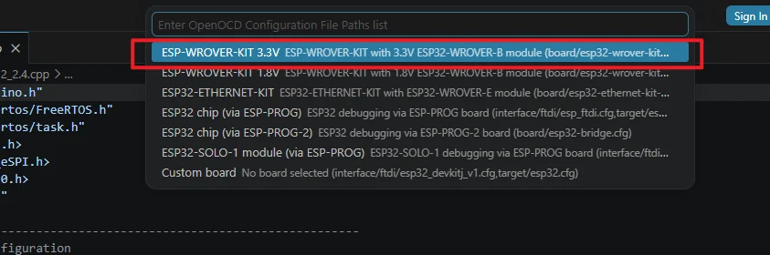
Select a configuration suitable for the classic ESP32, such as ESP-WROVER-KIT 3.3V. This lesson uses UART flashing; OpenOCD is not involved in writing, but selecting the correct configuration prevents the extension from repeatedly prompting that the configuration is missing.
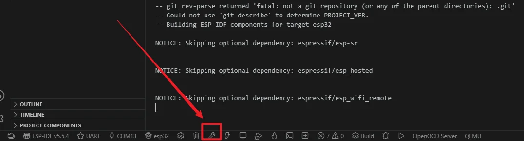
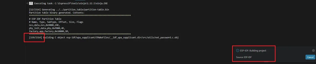
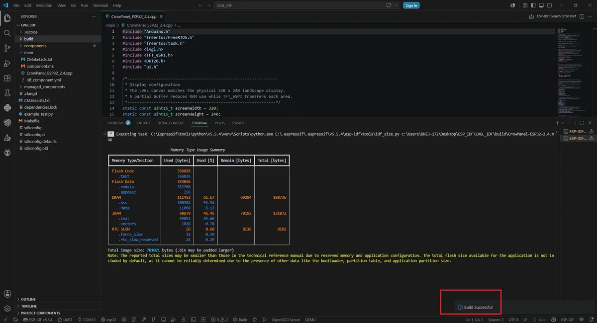
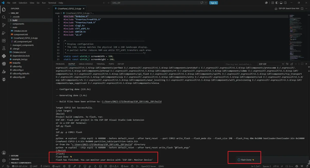
Click the Build (wrench) button in the status bar, or run idf.py build in the terminal. The first build takes longer; the bottom-right corner should indicate that the project build is complete.
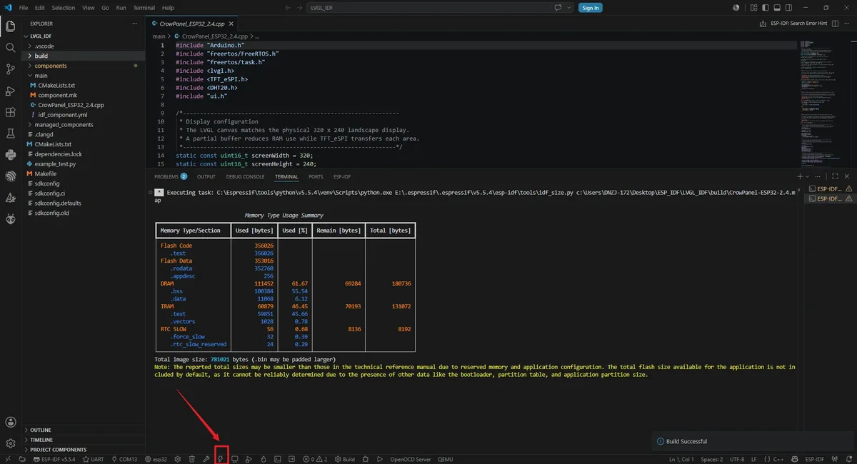
Confirm that the flashing method in the status bar is UART, then click the lightning-shaped Flash button; alternatively, run idf.py -p COMx flash, replacing COMx with the actual port. After writing finishes, the board resets automatically.
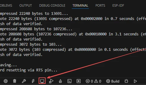
After uploading the code, click the Monitor button to open the serial port monitor; the baud rate is set to 115200 by default. After the monitor is opened, it should first display the ESP-IDF startup information, and then continuously print the serial port printing information set in your code.
5. Hardware Operation Steps
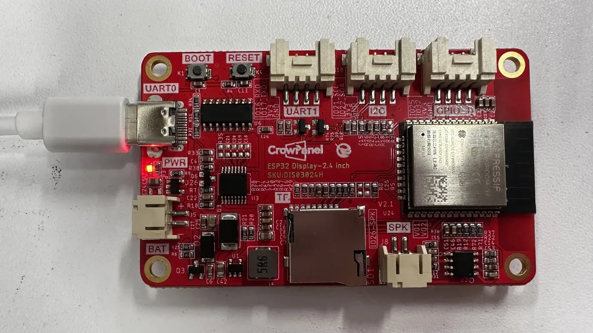
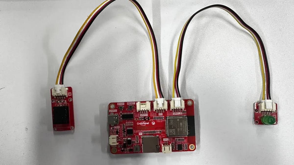
With the board powered off, connect the DHT20 module to the I2C interface of the board, confirming that SDA maps to GPIO22 and SCL maps to GPIO21. Connect the LED module to the interface labeled GPIO_D so that its signal line connects to IO25. Do not connect the signal line to a power pin, and do not plug or unplug modules while powered on.
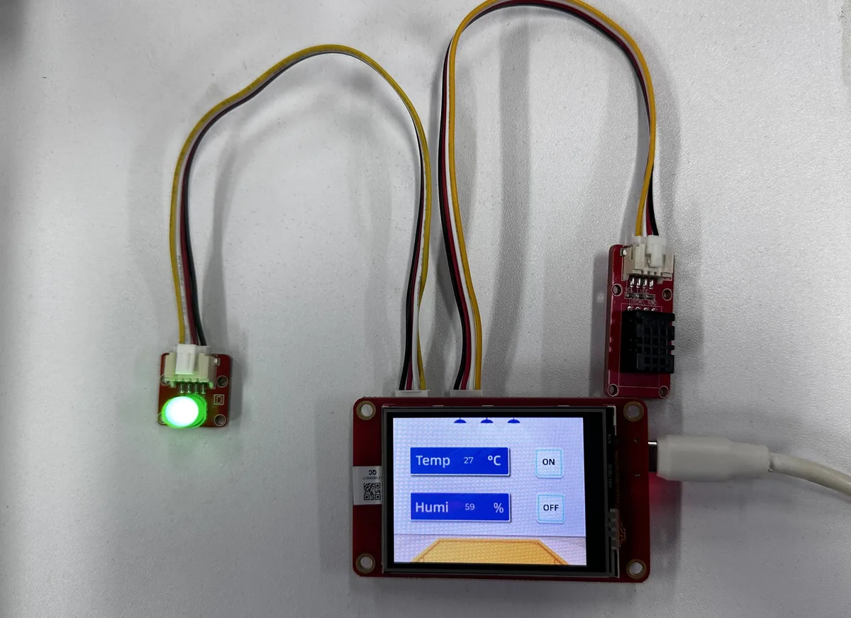
Reconnect the USB cable that supports data transfer. After the upload completes and the board resets automatically, the screen backlight should turn on, and the UI should show temperature, humidity, and the two buttons ON and OFF.
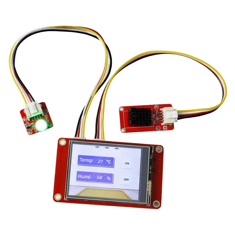
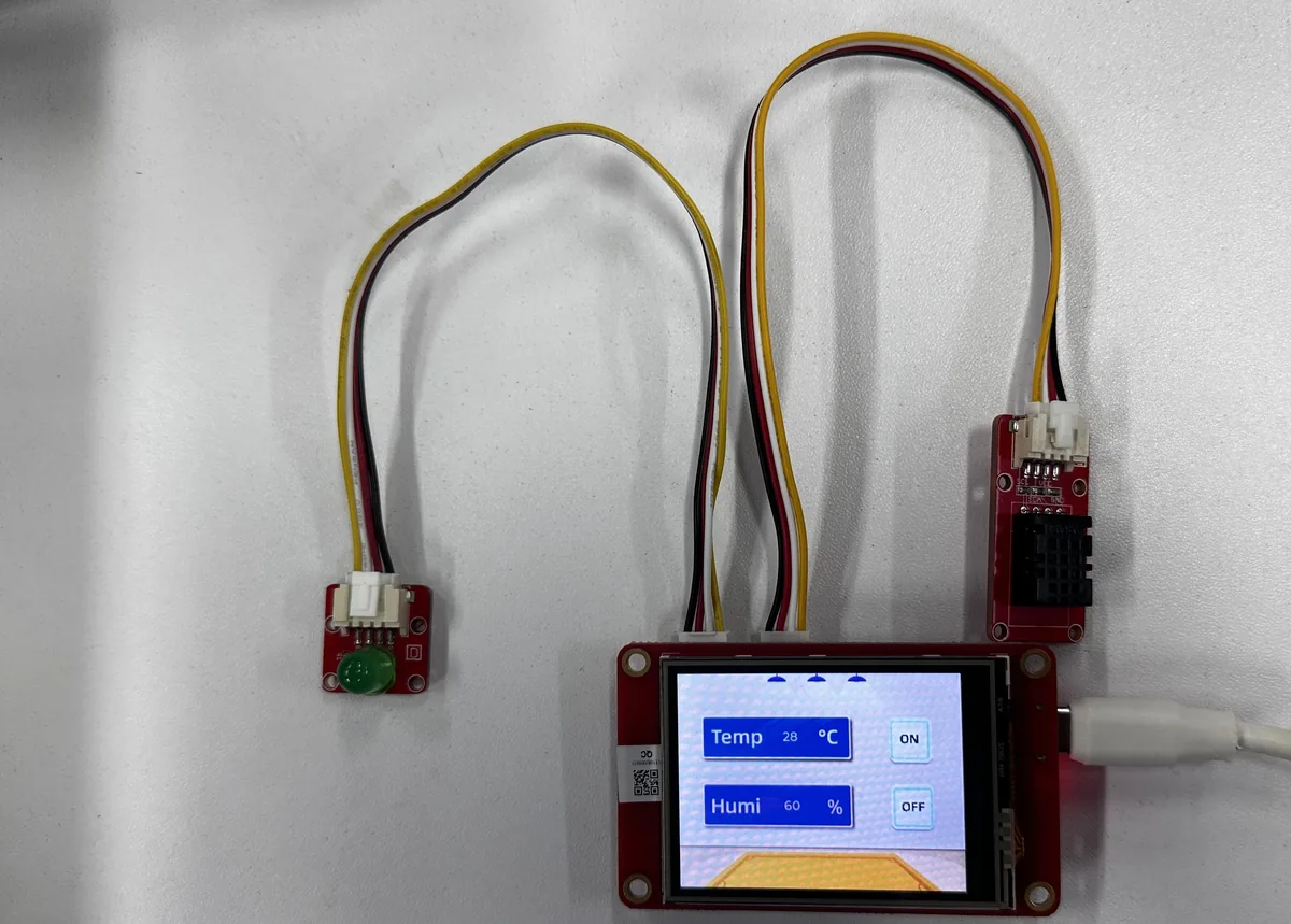
Tap ON and OFF in turn with your finger, and observe whether the LED lights up and goes out accordingly, while checking whether the serial monitor outputs the corresponding status. Do not press the screen with sharp or conductive objects.
ON -> LED on
OFF -> LED off
6. Key Code Explanation
6.1 Set Up the Low-Level Environment First in app_main()
// Receives the LED state selected by the C-based generated UI event code.
extern "C" int led = 0;

// Controls the TFT display and its resistive touch interface.
TFT_eSPI lcd = TFT_eSPI();

// Provides temperature and humidity measurements over I2C.
DHT20 dht20;

// Converts raw touch measurements into coordinates for this display.
uint16_t calData[5] = {189, 3416, 359, 3439, 1};

// Stores the latest touch position returned by TFT_eSPI.
uint16_t touchX, touchY;

/**
 * @brief Initialize the board and run the LVGL application task loop.
 *
 * ESP-IDF calls app_main() once after the scheduler and registered components
 * are ready. The function initializes Arduino compatibility before using its
 * peripheral APIs, then remains active as the application's main task.
 *
 * @param None.
 * @return Nothing; the function contains the permanent application loop.
 */
extern "C" void app_main()
{
  /*---------------------------------------------------------------
   * Start Arduino compatibility and basic peripherals
   * The LED begins off, and the DHT20 uses a 100 kHz I2C bus on GPIO22/21.
   *--------------------------------------------------------------*/
  initArduino();
  Serial.begin(115200);

  pinMode(25, OUTPUT);
  digitalWrite(25, LOW);

  Wire.begin(22, 21);
  Wire.setClock(100000);
  delay(100);
  if (dht20.begin() != 0) {
    Serial.println("DHT20 init failed");
  }
}
app_main() is where an ESP-IDF project truly starts running, and it is entered only once. Here we first call initArduino(), then use Arduino-style interfaces such as Serial, Wire, and pinMode().
Wire.begin(22, 21) specifies the I2C SDA and SCL; the pins must match the board wiring. Wire.setClock(100000) sets the bus speed to 100 kHz, which suits this combination of sensor and screen. A short delay is added before dht20.begin() to give the peripheral some power-up time.
6.2 Flush the LVGL Rendering to the LCD
void my_disp_flush(lv_display_t *disp, const lv_area_t *area, uint8_t *px_map)
{
  // LVGL includes both boundary pixels in the dirty rectangle.
  uint32_t w = (area->x2 - area->x1 + 1);
  uint32_t h = (area->y2 - area->y1 + 1);

  // Transfer the rendered rectangle to the LCD over SPI.
  lcd.startWrite();
  lcd.setAddrWindow(area->x1, area->y1, w, h);
  lcd.pushColors((uint16_t *)px_map, w * h, true);
  lcd.endWrite();

  // Let LVGL reuse its partial buffer after the transfer completes.
  lv_display_flush_ready(disp);
}
This function's job is simple: after LVGL finishes drawing a region, it sends that region of pixels to the screen. It does not refresh the whole screen, but only the changed rectangular area, so it is faster.
area holds the range to be updated, and the +1 is because the coordinates are inclusive of the boundary pixels. After flushing, you must call lv_display_flush_ready(); otherwise LVGL will keep thinking this region has not finished sending, and subsequent refreshes will not connect.
6.3 Align the Touch Coordinates with the Current Landscape Orientation
void my_touchpad_read(lv_indev_t *indev, lv_indev_data_t *data)
{
  // 400 is the pressure threshold used by this ESP-IDF calibration.
  bool touched = lcd.getTouch(&touchX, &touchY, 400);
  if (!touched)
  {
    // Report release so LVGL can complete and cancel touch gestures correctly.
    data->state = LV_INDEV_STATE_RELEASED;
  }
  else
  {
    // Mirror X because the installed landscape orientation reverses that axis.
    data->state = LV_INDEV_STATE_PRESSED;
    data->point.x = screenWidth - touchX;
    data->point.y = touchY;
  }
}
calData is the touch calibration data, used to convert raw touch values into screen coordinates. 400 is the touch pressure threshold; if it is too high the screen may fail to register a press, and if too low it may cause false touches.
This project also performs the mirroring screenWidth - touchX, because the current landscape mounting orientation is opposite to the raw coordinate direction. If the tap position is left-right reversed, check the calibration data and this mirroring step first; do not rush to modify the UI widget coordinates.
6.4 Refresh the UI, Read Sensors, and Control the LED in the Main Loop
uint32_t last_sensor_ms = 0;

while (1)
{
  // Service LVGL timers and pending input on every task iteration.
  lv_timer_handler();

  // Limit sensor reads to once per second to avoid unnecessary I2C traffic.
  uint32_t now = millis();
  if (now - last_sensor_ms >= 1000) {
    last_sensor_ms = now;
    // Read both values together so the labels use one sensor sample.
    int temperature = 0;
    int humidity = 0;
      if (dht20.readTempHumidity(&temperature, &humidity) == 0) {
        // Convert readings to text; LVGL copies each label string immediately.
        char dht_buffer[8];
      snprintf(dht_buffer, sizeof(dht_buffer), "%d", temperature);
      lv_label_set_text(ui_Label1, dht_buffer);
      snprintf(dht_buffer, sizeof(dht_buffer), "%d", humidity);
      lv_label_set_text(ui_Label2, dht_buffer);
    }
  }

  // Apply the ON/OFF state written by the generated UI event handlers.
  digitalWrite(25, led ? HIGH : LOW);
  // Yield the task briefly so other ESP-IDF work can run.
  vTaskDelay(pdMS_TO_TICKS(10));
}
This loop is what the whole program keeps doing: on each iteration it first services LVGL, then reads the DHT20 once every 1 second. This keeps the UI smoothly refreshing while avoiding reading the sensor too often.
The temperature and humidity labels are updated only when readTempHumidity() succeeds; if the read fails, the previous frame's values are retained. digitalWrite(25, led ? HIGH : LOW) controls the LED based on the state of the UI button. vTaskDelay() yields the CPU so the system is not always occupied by this single task.
6.5 Let the UI Event and the Main Program Share led
/* main/CrowPanel_ESP32_2.4.cpp */
// Define the shared LED state with C linkage for the generated UI code.
extern "C" int led = 0;

/* components/UI/ui_Screen1.c */
// Refer to the same state from the C-compiled button event handlers.
extern int led;

// A completed click on the ON button requests GPIO25 high.
if (event_code == LV_EVENT_CLICKED) {
    led = 1;
}
The UI files generated by SquareLine are compiled as C, while the main entry main.cpp is C++. The role of extern "C" is to let these two files find the same led variable.
After the button is pressed, the UI event changes led to 1 or 0, and the main loop then lights up or turns off GPIO25 based on this value. If you remove this declaration, you will typically get a link-time error that led cannot be found.
7. UI Asset Creation and Integration
This section uses SquareLine Studio 1.6.1 to demonstrate the UI creation process again. The course already provides the exported UI files; beginners can first read this section to understand the flow, then directly use the project's files to complete the build. When creating a new project, you must select LVGL 9.1.0;
How to download SquareLine Studio: https://www.elecrow.com/wiki/Create_LVGL_UI_with_SquareLine_Studio.html
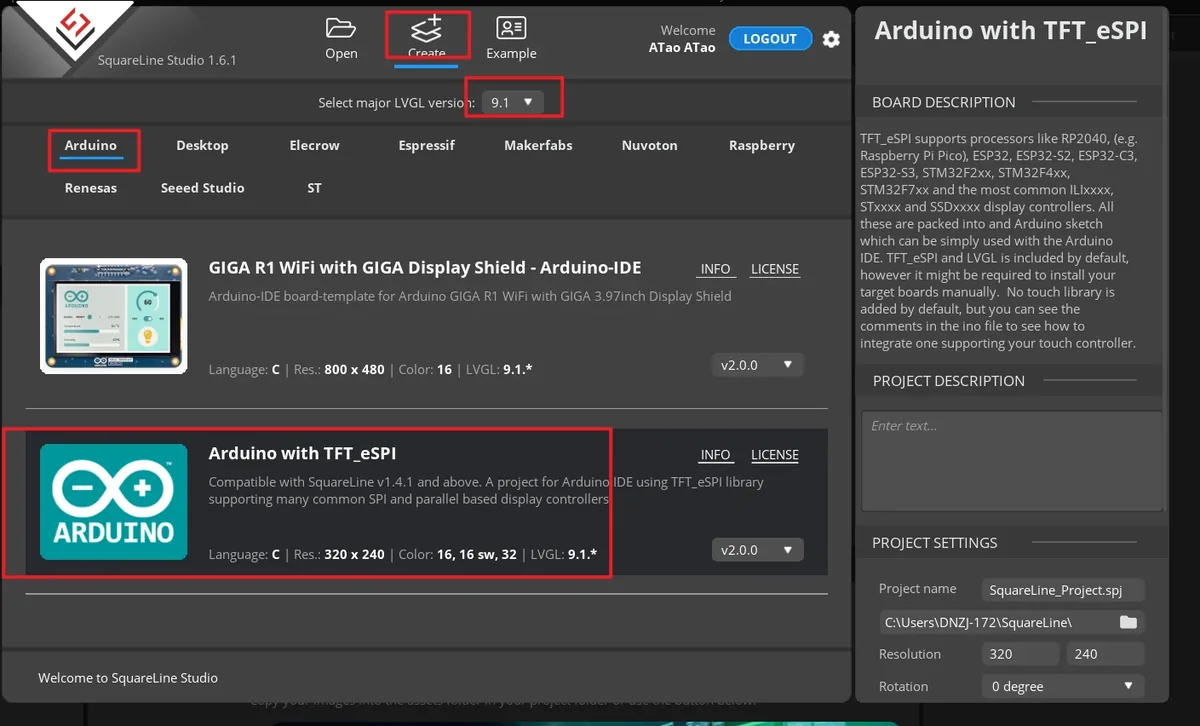
Launch SquareLine Studio 1.6.1, click Create, and select the Arduino with TFT_eSPI template for the Arduino platform. This template generates the UI file framework suitable for Arduino and TFT_eSPI projects.
Note: When the Arduino framework is selected, SquareLine Studio shows only the Arduino with TFT_eSPI option. It generates template code suitable for TFT_eSPI, but SquareLine Studio also supports other graphics libraries; when switching to other hardware, you need to modify the display code according to the actual library.
Enter the project name, set the LVGL version to 9.1.0, the resolution to width 320 and height 240, and the color depth to 16 bit, then click CREATE. After creation, the canvas should be landscape 320×240.
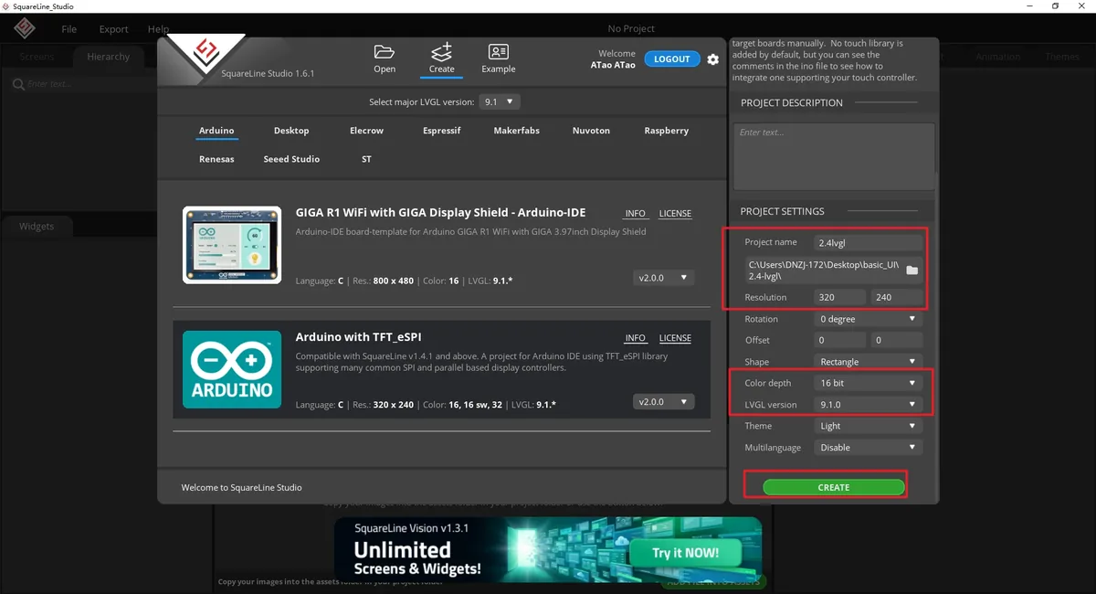
Explanation: A 16 bit color depth can represent 65,536 colors, using the RGB 5:6:5 pixel representation. Keep it consistent with the project's color configuration.
After the project opens, select Screen1 in the Screens panel on the left, and confirm that the central canvas is blank and the Inspector on the right shows the Screen properties. All subsequent widgets are added to this page.
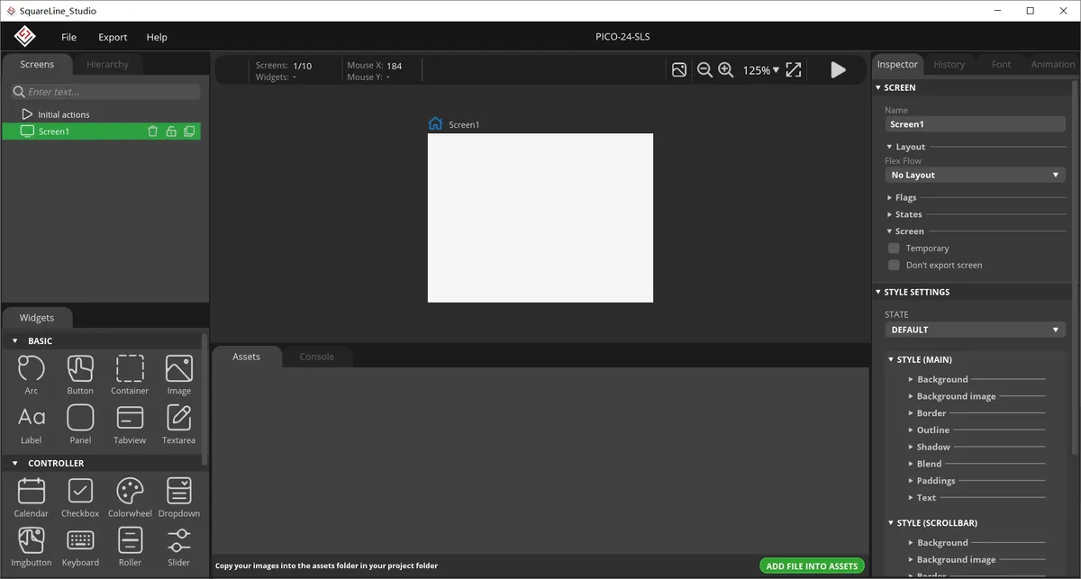
In the Assets area, click ADD FILE TO ASSETS, and import background.png, on.png, and off.png from LVGL-Assets-320x240/ in order. After import, you should see three thumbnails.
Material link:
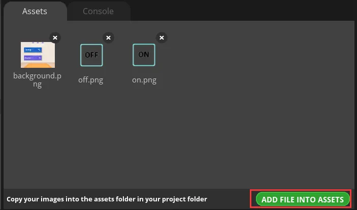
Note: Image assets support the PNG format only; the pixel dimensions of an image should be smaller than the project screen size; a single image should not exceed 100 KB, and is best kept within 30 KB, to avoid affecting display smoothness.
Select Screen1, expand STYLE SETTINGS > STYLE (MAIN) > Background on the right, and enable the background image setting.
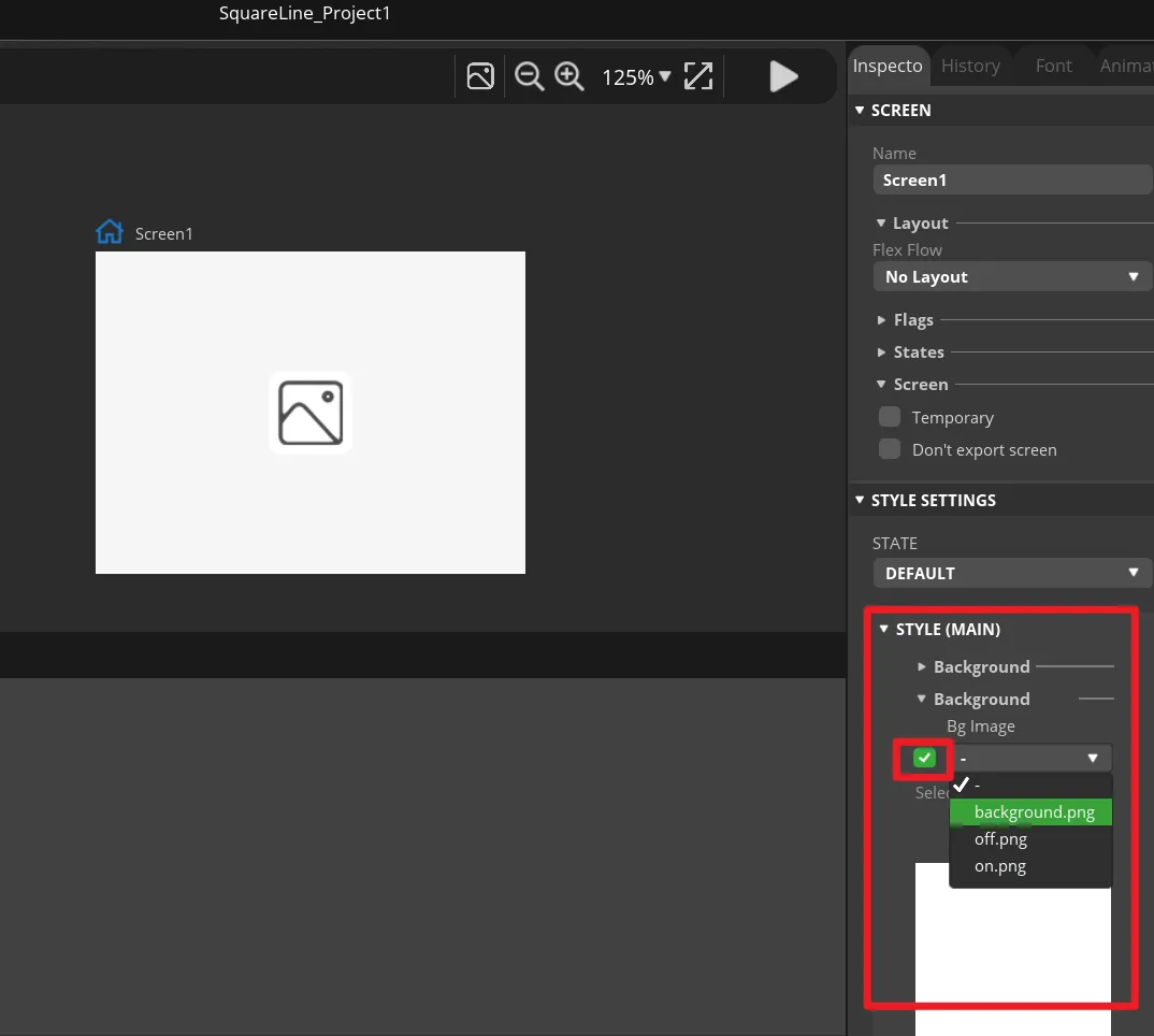
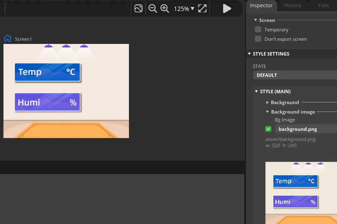
In Bg Image, select background. The canvas should immediately display the course background image, with the background fully covering the 320×240 page.
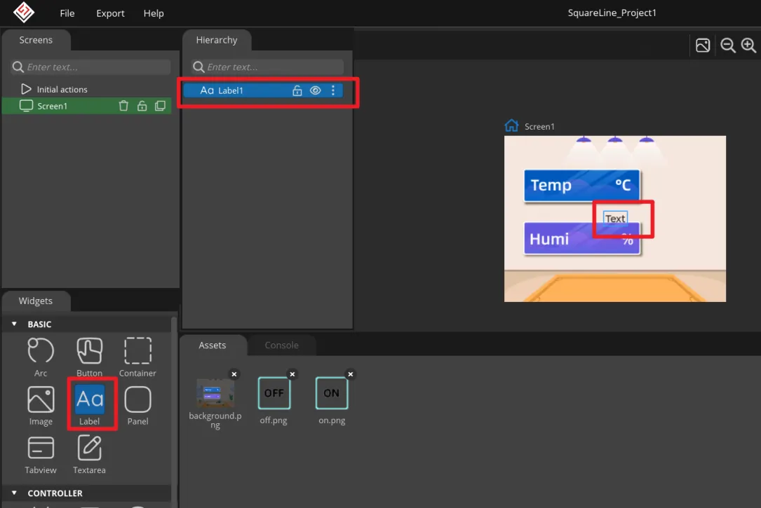
In the left Widgets, click Label to add Label1 to Screen1. This label will be updated by the program to show the temperature value.
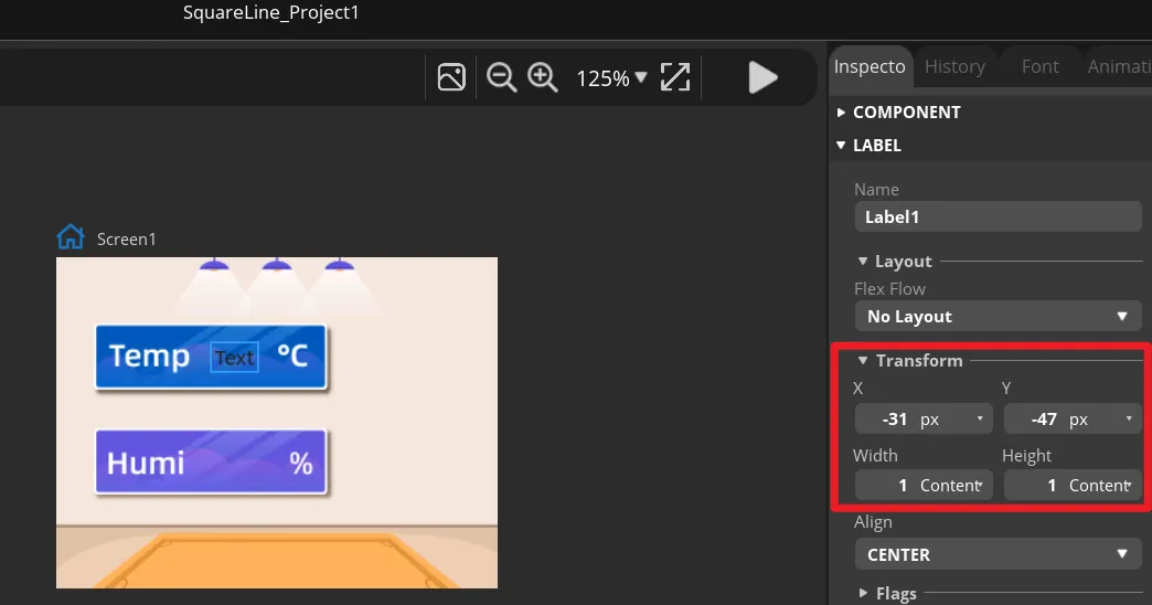
Select Label1, and in Transform adjust the X and Y position along with the width and height so that it sits within the temperature display area of the background image. You can also drag it first and then fine-tune using the numeric values.
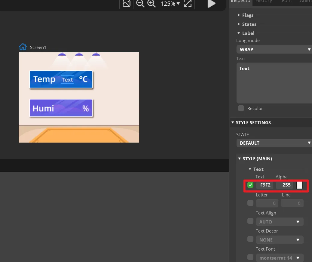
In Label1's STYLE (MAIN), change the text color to white and set an appropriate font size. The text on the canvas should be clearly visible and should not extend beyond the background frame.
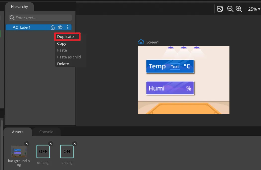
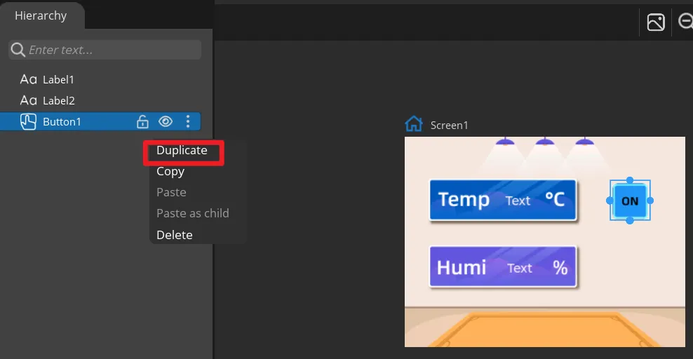
Right-click Label1 and choose Duplicate to generate Label2, then move it to the humidity display area. Keep the Label1 and Label2 names, because the main program updates them by name.
Select the two Labels respectively, and in Text enter default numbers for easy preview. These are only design-time placeholder values; once the development board runs, they will be replaced by the DHT20 readings.
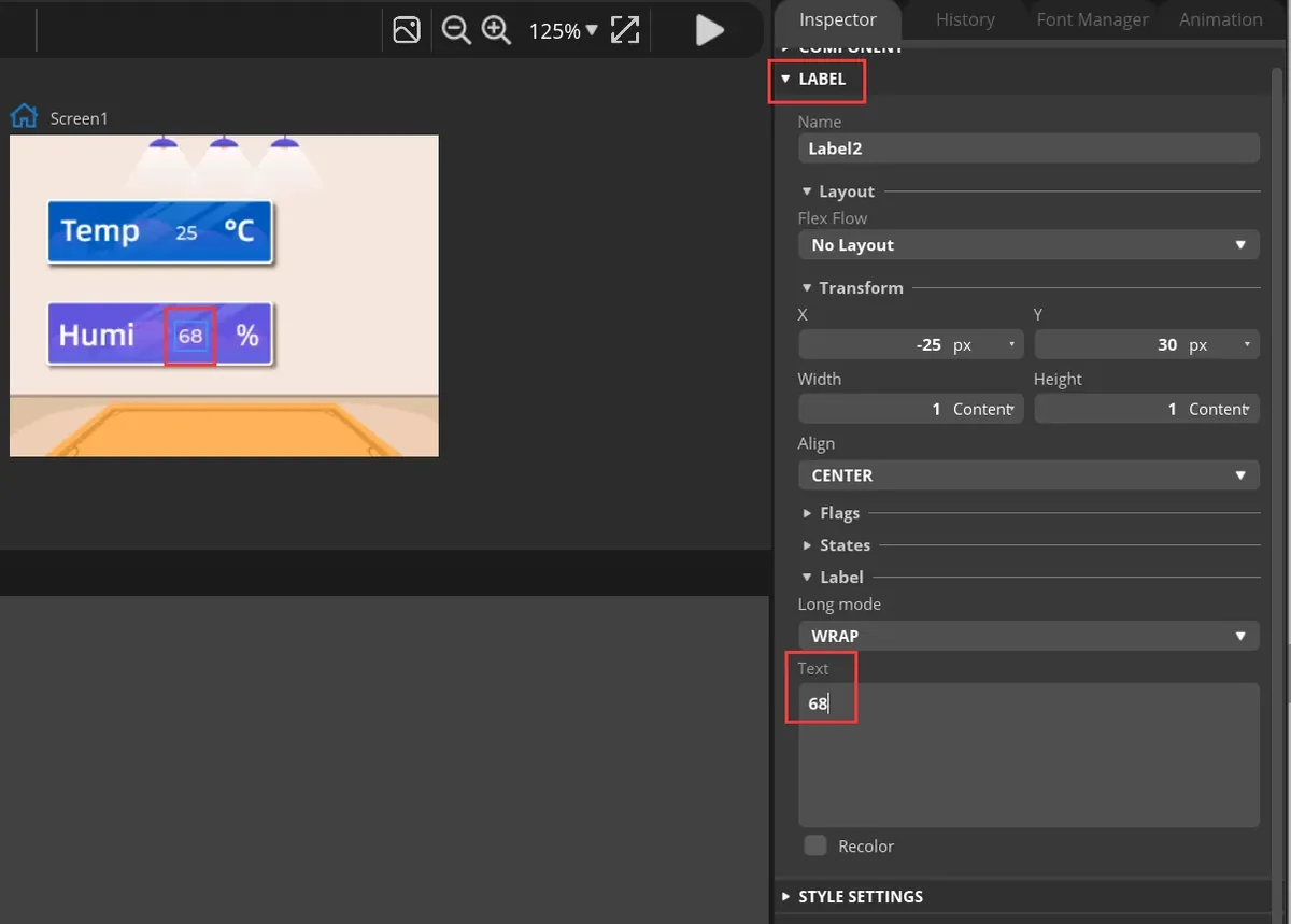
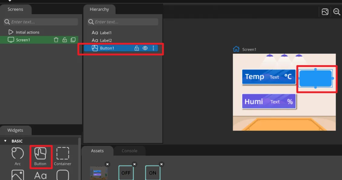
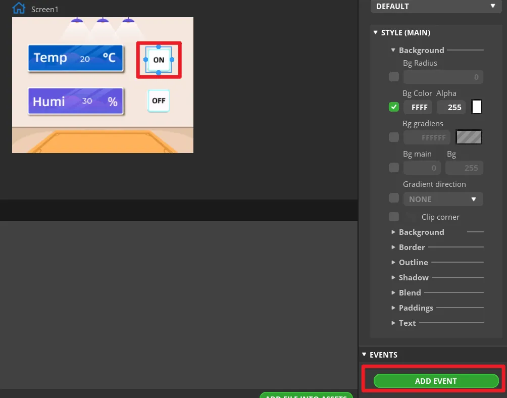
In Widgets, click Button to add Button1, and drag it to the ON area on the right side of the interface.
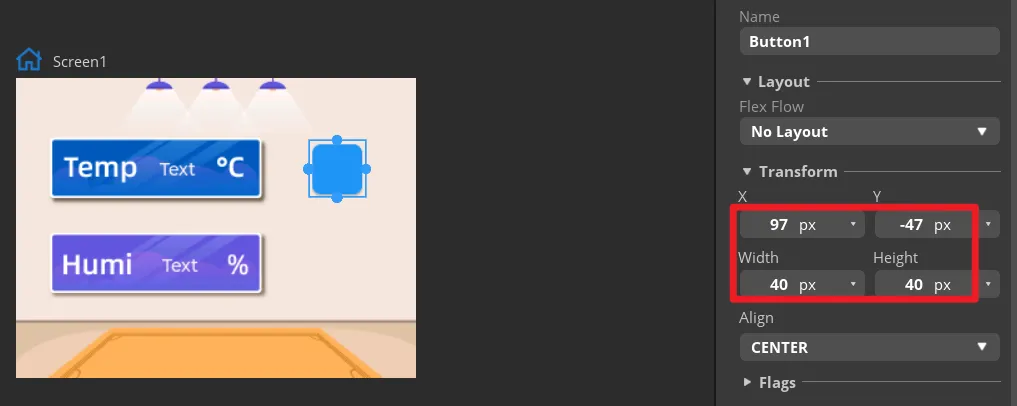
In Transform, set the size of Button1 and adjust its position so that the button aligns with the ON area in the background.
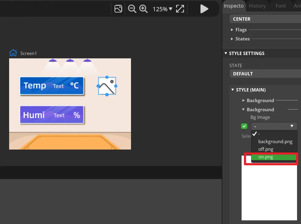
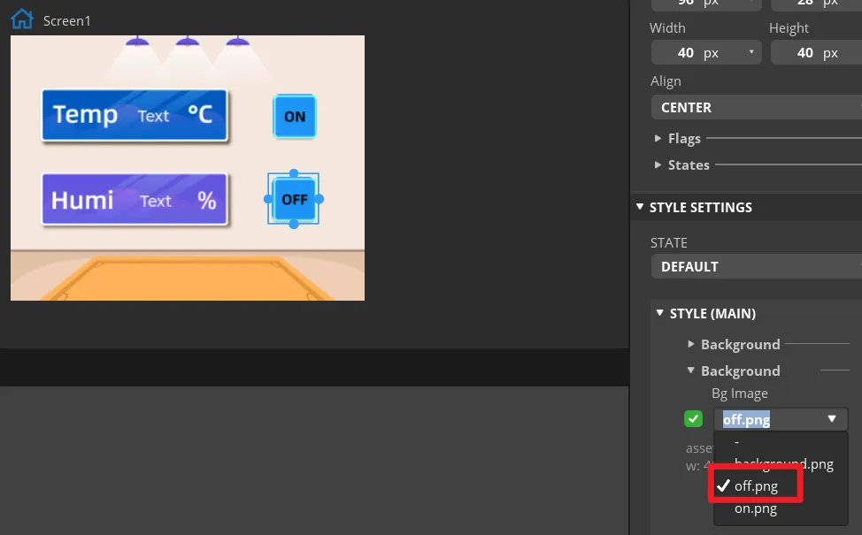
Expand Button1's STYLE (MAIN) > Background and select on.png as the background image. An ON icon should appear on the canvas.
Duplicate Button1 to get Button2, move it to the OFF area, and change the background image to off.png. Keep the Button1 and Button2 names to make them easier to match with the exported event functions.
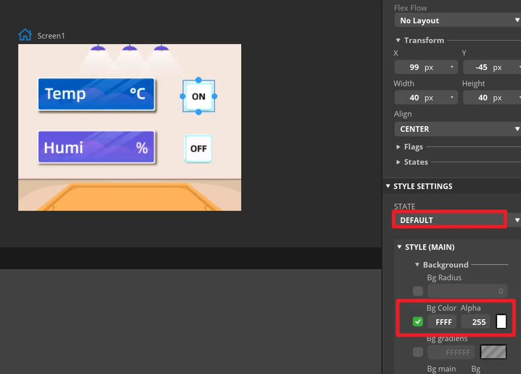
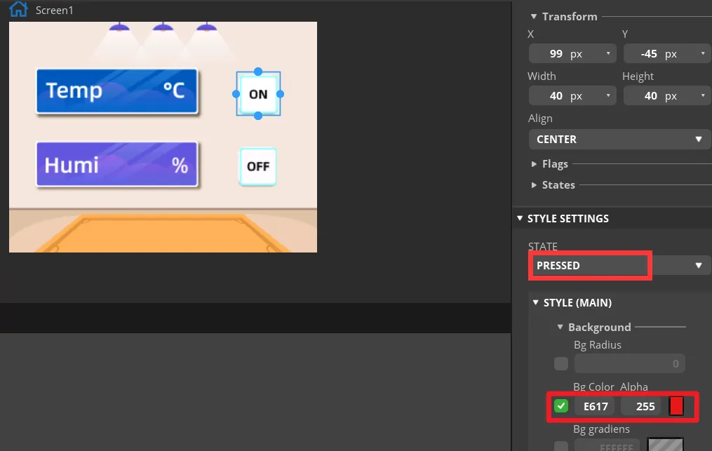
In the STATE settings of both buttons, check the DEFAULT and PRESSED states. The pressed state can use a noticeable color change, so that you can tell in the preview whether a button is pressed. In "Inspector" -> "Style Settings" -> "State", set the displayed background color to white, and when in the "checked state" it displays red. Set the same parameters for the "Off" button.
Select Button1 and click ADD EVENT.
Select "CLICKED" as the trigger condition, and in "Action" select the triggered event. The LED control function will be implemented later by modifying the generated program.
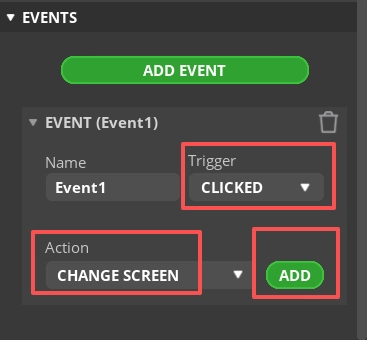
Note: Since the buttons will ultimately control the LED on/off, you can add any event here first so that the exported UI file generates the button event code framework; the LED control code will be modified in subsequent steps.
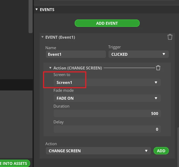
Complete this event. Here, I choose to switch screens, that is, switch to the Screen1 screen.
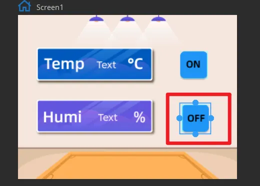
Add the event to Button2 in the same way (state is "Off").
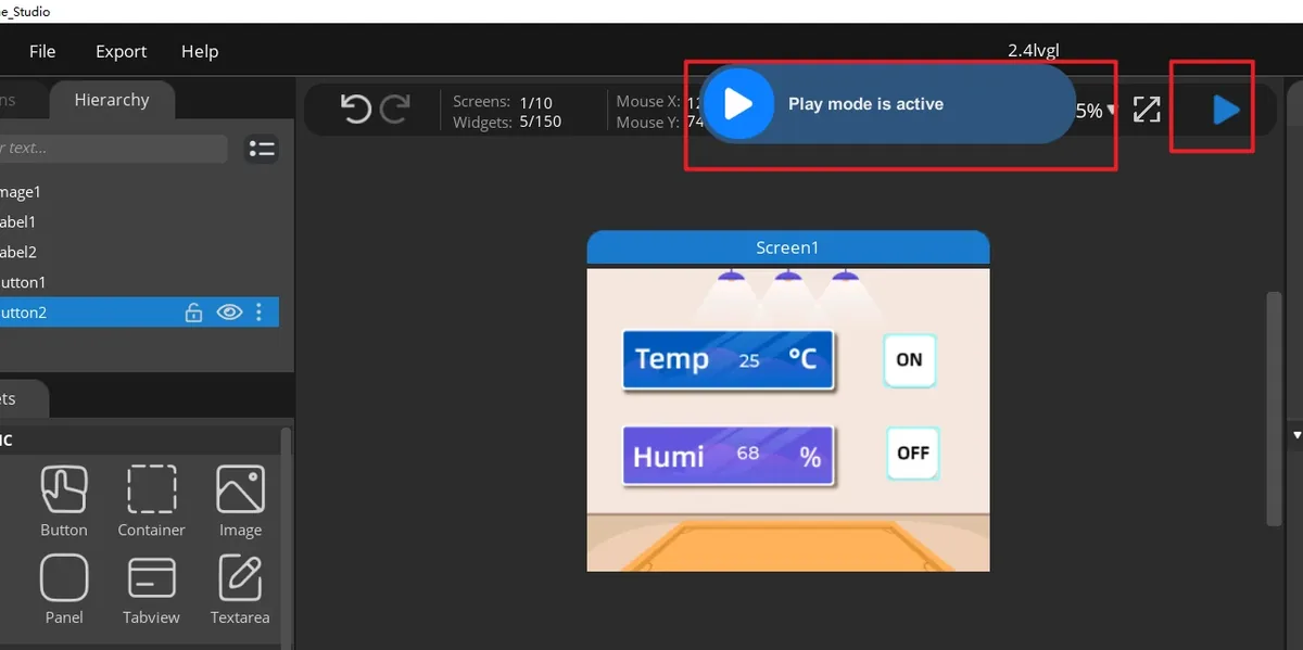
Click Run.
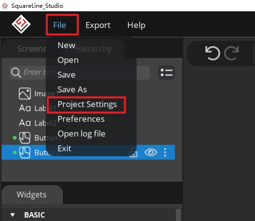
Open File > Project Settings, then make the relevant settings for the exported files.
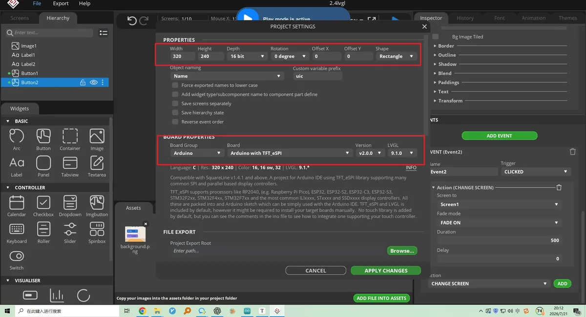
Set the export directory to an easy-to-find pure-English path, create a new output folder, and fill in and confirm that the LVGL Include Path is lvgl.h; after confirming, click APPLY CHANGES.
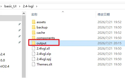
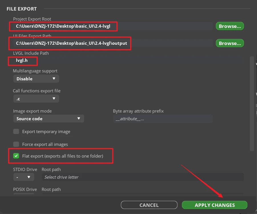
Tip: After selecting Flat export, all output files will be placed in the same folder, and the program will not need to modify the file paths. If Flat export is not selected, the files will be scattered across different folders and the compiler may not be able to recognize them automatically; usually you would have to modify the paths manually, so it is recommended to keep it checked.
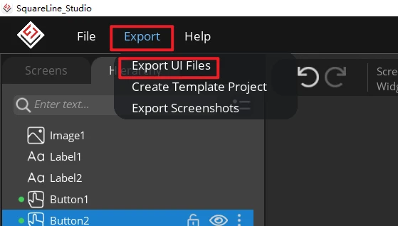
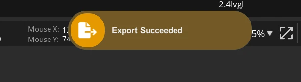
Click Export > Export UI Files. After the export is complete, ui.c, ui.h, ui_Screen1.c, the event files, helper files, and the image array files should appear in the target directory.
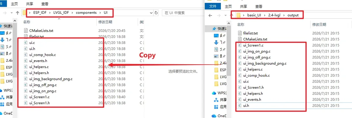
Copy all the exported UI files (.c and .h files) into the UI folder under Components in the project, replacing them with the lvgl 9.1 version.
8. Observed Behavior
After flashing and resetting, the LCD first displays black; about 300 ms later, GPIO27 goes high, the backlight turns on, and the 320×240 UI loads. The temperature and humidity integers are displayed slightly left of center on the screen, with the ON and OFF image buttons shown on the right side. When the DHT20 is working normally, the labels update about once per second; if the environment stays unchanged for a short time, the values remaining the same is normal.
After clicking ON, the UI event sets led to 1 and GPIO25 outputs a high level; after clicking OFF, it outputs a low level.
ON → LED lights up
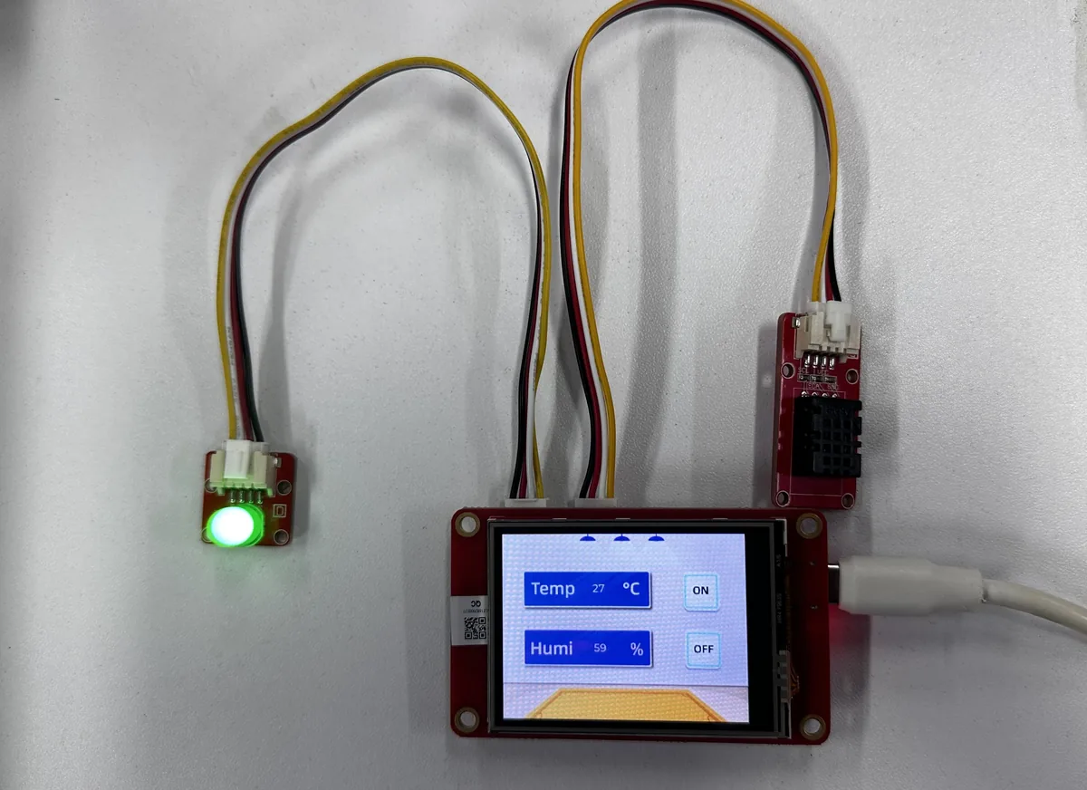
OFF → LED turns off