NRF1262 module node to node communication
In this lesson, we will mainly look at how to use the NRFLR1262 to transmit data.
The NRFLR1262 is a wireless communication module specially designed for developing low-power, long-range IoT applications. It integrates Semtech's SX1262 and Nordic's nRF52840, combining Semtech's LoRa technology with Nordic's low-power Bluetooth technology. This module not only supports long-range wireless communication via LoRa, but also features Bluetooth communication, making it suitable for a variety of IoT application scenarios.
Features of the NRFLR1262 Module:
High Performance: Maximum transmit power up to +20 dBm, supports data rates from 0.018 to 62.5 kbps, sensitivity of -125.5 dB @ SF12/BW=125kHz, and a link budget of 170 dB.
Ultra-Low Power Consumption: Sleep current as low as 5 μA.
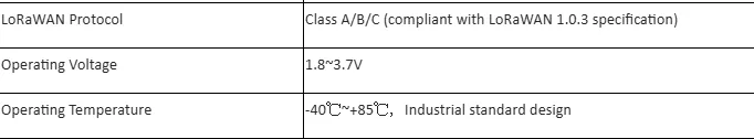
Frequency Support: Supports global LoRa & LoRaWAN ISM frequency range of 850~930 MHz, and LoRa point-to-point (P2P) communication; the nRF52840 Bluetooth 5.3 SoC supports low-power Bluetooth, Bluetooth Mesh, NFC, Thread, and Zigbee.
Built-in AT Command Firmware: Supports custom product development using SDK, and allows easy use of the AT command set via the UART interface.
Long-Range Communication: Communication distance can reach up to 10 km.
Rich Peripherals: The module exposes multiple GPIO interfaces including UART, I2C, and ADC, providing great flexibility.
Voltage and Temperature Monitoring:
As shown in the figure below, we use the NRFLR1262 module with each interface connected to a sensor in order to collect data from all sensors. The data is then transmitted to another NRFLR1262 module using LoRa technology, and finally, the received data is viewed through the serial port.
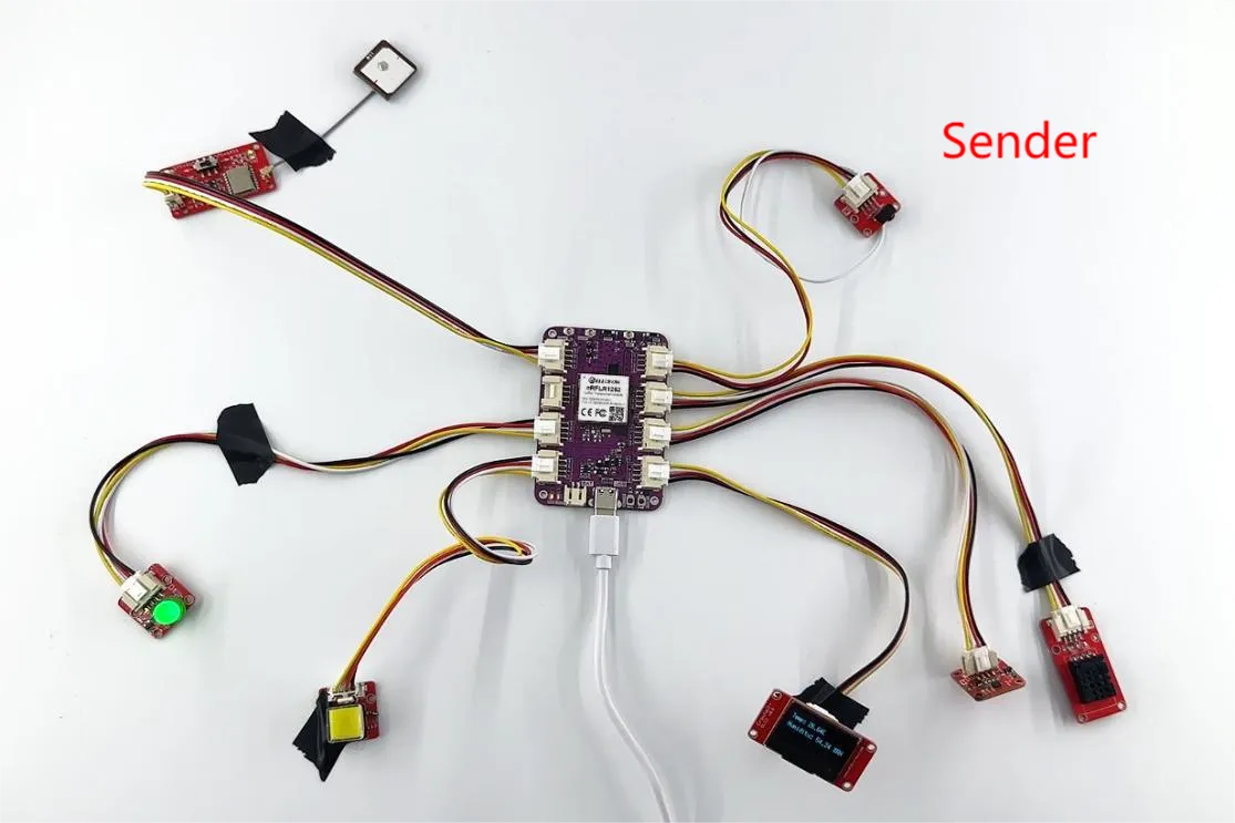
Next, let’s explore this together.
First, open the code files.
The NRFLR1262_Sender file is used to collect sensor data and transmit it.
The NRFLR1262_Receive file is used to receive the data.
Code Link:
Let’s first introduce the code structure of the transmitter.
We will explain it by module:
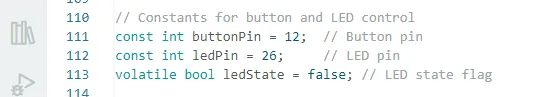
Bulb: Connected to the NRFLR1262 module's GPIO_D interface, which corresponds to pin 26.
Button: Connected to the NRFLR1262 module's GPIO_D interface, which corresponds to pin 12.
DHT20 Temperature and Humidity Sensor: Connected to the NRFLR1262 module's I2C interface, which corresponds to pins 13 and 14.
Accelerometer: Connected to the NRFLR1262 module's I2C interface, also on pins 13 and 14.
u8g2 Display: Connected to the NRFLR1262 module's I2C interface, using pins 6 and 7.
IR Receiver: Connected to the NRFLR1262 module's UART interface, which corresponds to pins 22 and 24.
GPS Module: Connected to the NRFLR1262 module's GPIO_A interface, which corresponds to pins 28 and 29.

Next, let’s talk about the implementation of the bulb and the button.
Bulb and Button
The main function is to turn the bulb on or off by pressing the button.
First, define the pins for the two interfaces.
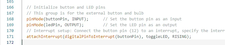
Then, in the setup function, set the pin modes for input and output, and configure the interrupt condition.
Interrupt Configuration:
Connect the button pin (12) to an interrupt, assign the interrupt service routine to toggle the LED, and set the trigger condition to rising edge (i.e., when the button is pressed).
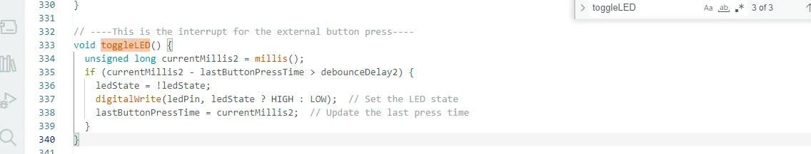
And set the logic for turning on and off.
DHT20 Temperature and Humidity Sensor
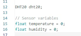
Initialize the libraries and variables to be used first.
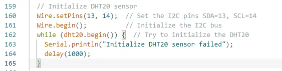
Then initialize the temperature and humidity sensor in setup
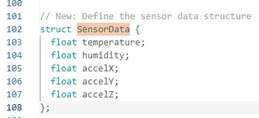
The struct defined here contains the values for temperature, humidity, and acceleration in three directions.
The purpose is to transmit all of this data together to another NRFLR1262 module.
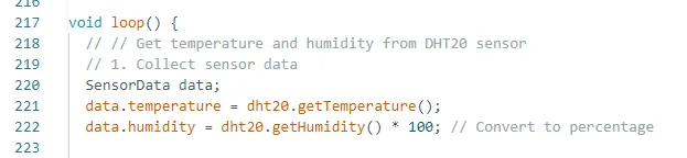
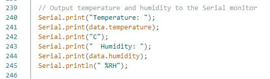
Next, in the loop function, the temperature and humidity values are obtained and stored in the corresponding temperature and humidity variables within the struct.
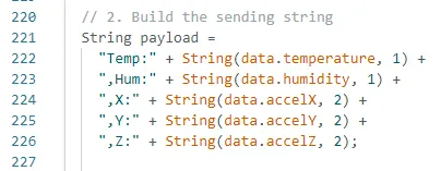
After obtaining the temperature and humidity values, you can print the values to the serial port for viewing.
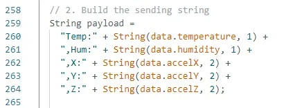
Then, combine these values into the payload variable, making it easier to transmit them together.
Here, LoRa technology is used to transmit the data.
Accelerometer
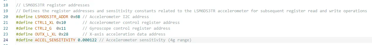
First, refer to the technical manual of the LSM6DS3 accelerometer sensor to explain and define its related registers.
Since both the accelerometer and the temperature and humidity sensor use the I2C protocol, their pins have already been initialized.

Then, in the loop function, repeatedly obtain the acceleration values for the three directions.
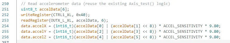
The writeRegister and readRegister functions are custom functions that we’ve written.
(You can refer to the code for details; the comments in the code are very detailed, so we won’t explain them here.)
writeRegister: Writes data to a register.
readRegister: Reads data from a register.
After obtaining the acceleration data, combine it into the payload variable, making it easier to transmit the data together.
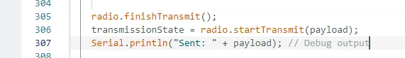
Finally, transmit the data to another NRFLR1262 module.
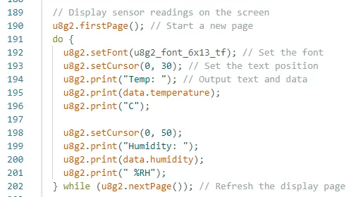
U8g2 display screen
In this experiment, we also added the display functionality, mainly to show the temperature and humidity values.
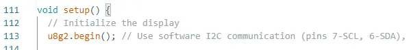
At the beginning of the code, we initialize the display configuration.
Although the display also uses the I2C interface, here we are using software I2C.

And in the setup function, initialize the display.
Then, in the loop function, set up the screen display and continuously update the values being displayed.
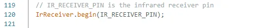
IR Receiver
Initialize the pin 24, which is connected to the infrared sensor.

And in the setup function, initialize the infrared receiver sensor.
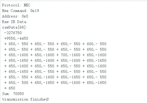
In the loop function, continuously process and receive the infrared signals sent by the remote control.


After receiving the infrared signal, the corresponding information will be displayed in the serial monitor, as shown in the figure below.
GPS positioning module
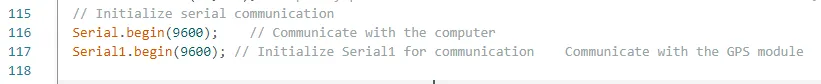
Since the GPS module is connected to the UART interface, we initialize the UART interface pins 28 and 29.

And initialize the baud rate required for the serial communication.
Serial1.available() will return the number of bytes available in the UART 1 input buffer. If the return value is greater than 0, it indicates that there is data available to be read.
When Serial1.available() returns a value greater than 0, the program enters the while loop. Inside the loop, the Serial1.read() function is used to read one byte of data from UART 1 and store it in the incomingByte variable. Then, Serial.print(incomingByte) is used to print the received data via the serial port (Serial), allowing you to view the received GPS signal data in the serial monitor.

As you can see here, we haven't processed the received GPS signals. If you're interested, you can experiment with it to extract the desired latitude and longitude information.
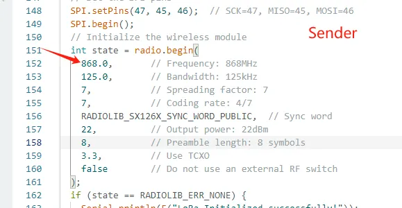
LoRa module

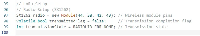
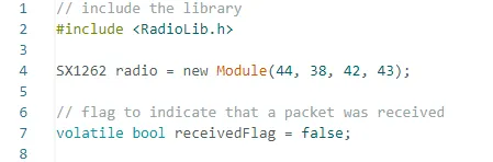
First, initialize the pins for the LoRa module.
You can open the schematic diagram we provided.
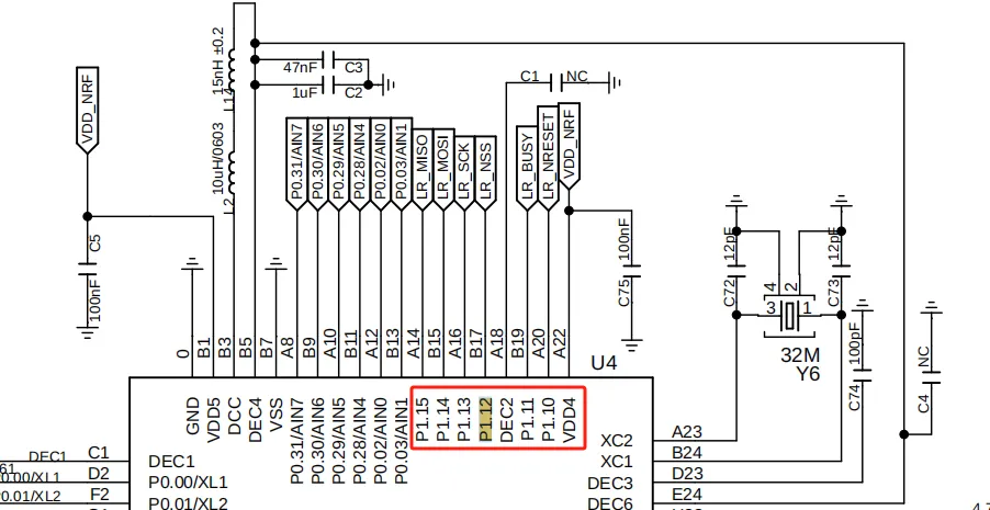
In our schematic diagram, P1.12 represents pin 44.
Explanation: P1 represents 32, and the number after the decimal point (12) means adding 12 to 32, so 32 + 12 = 44.
If it were P0.12, it would represent pin 12.
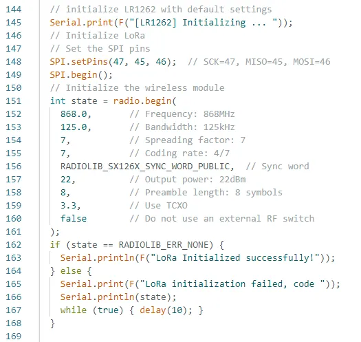
In the setup function, configure the relevant settings for the LoRa module.
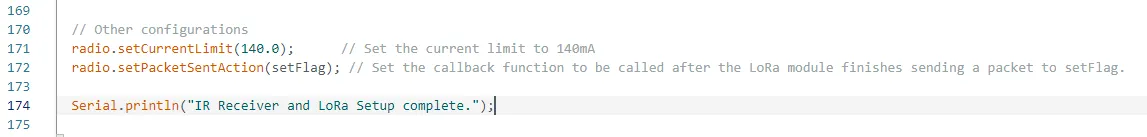
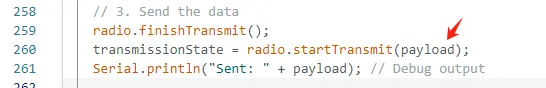
Finally, in the loop function, repeatedly send the data collected from the sensors.
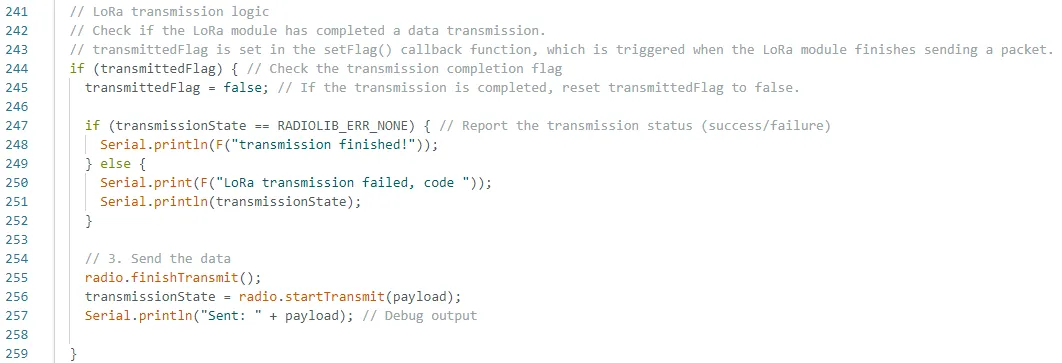
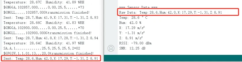
The overall data sent by the transmitter, as shown in the figure below.
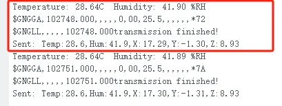
This is the overall structure of the transmitter.
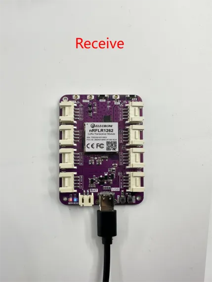
Next, let's take a look at the code structure of the receiver.
Receiving end
The receiver also starts by initializing the pins for the LoRa module.
The most important thing is that the frequency band must match the frequency band used by the transmitter.

Next, the data sent from the transmitter needs to be parsed.
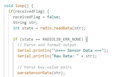
The parseSensorData function is a custom parsing function I wrote, so we won’t go into further detail here. The purpose of this function is to decode the data that was packaged and sent.
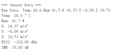
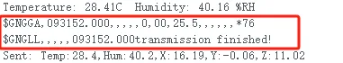
You can compare the sent message with the received data to verify the accuracy and integrity of the transmission.
Perfect! The LoRa module successfully transmitted the data!
That concludes the explanation of the code for both the transmitter and receiver.
NOTE:
Finally, here are some important points to note during actual operation:
-
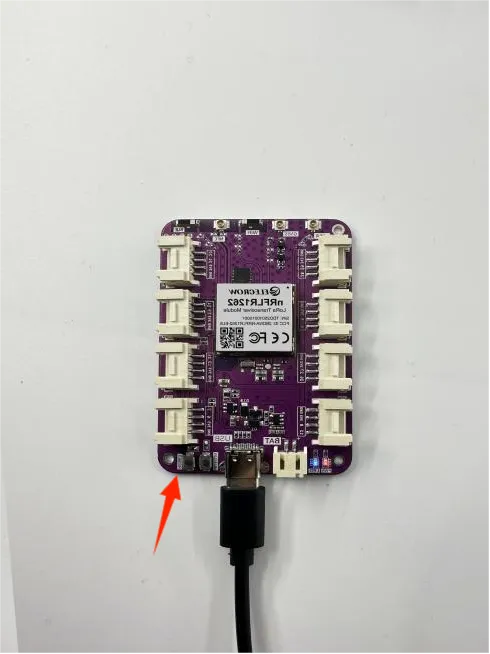
Before programming, you need to press the RESET button twice.
If you don’t press it, the serial port won’t allow the programming process.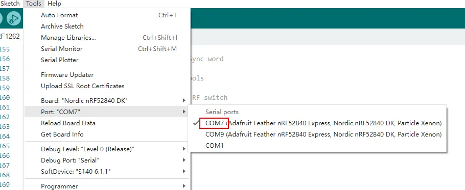
After pressing the RESET button twice.
A new serial port number will appear.
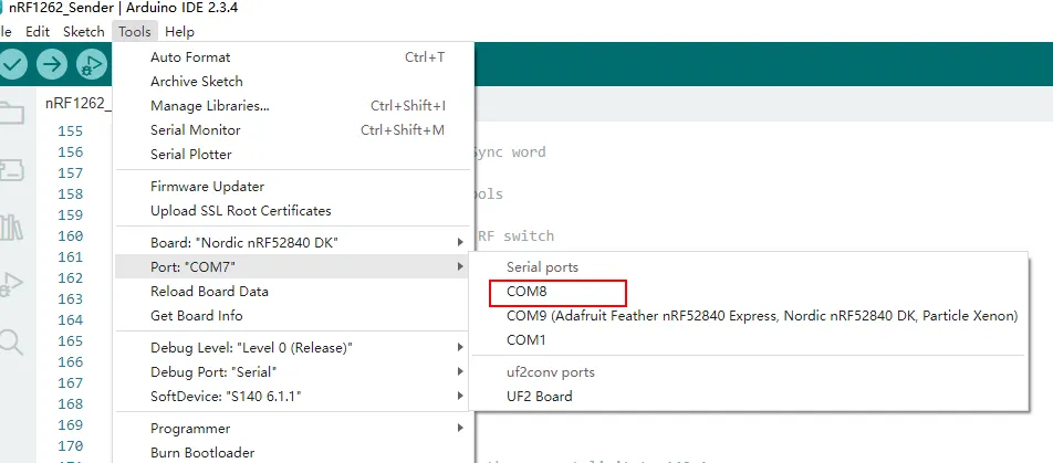
Select this serial port number for burning.
-
Since the nRFLR1262 uses the nRF52840 as the main control chip, you need to install the nRF52 development board.
-
Open the Arduino IDE.
-
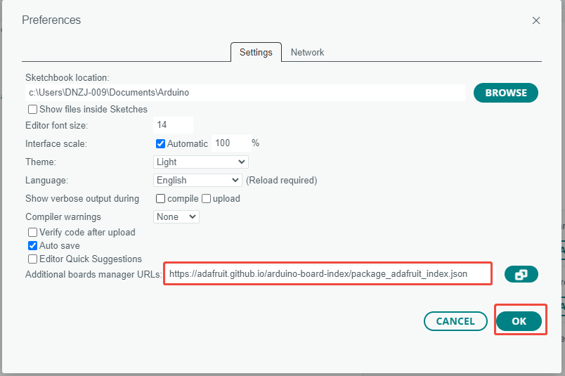
Go to File > Preferences (or Arduino > Preferences, depending on your operating system).
-
In the "Additional Board Manager URLs" field, add the following URL:https://adafruit.github.io/arduino-board-index/package_adafruit_index.json. If there are already other URLs, make sure to separate them with commas or new lines.
-
Click "OK" to save the settings.
-
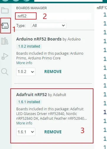
Navigate to Tools > Board > Boards Manager.
-
In the search box, type "Adafruit nRF52", find "Adafruit nRF52 by Adafruit", and click "Install".
-
Once installation is complete, you can select the appropriate board model from the Tools > Board menu.
-
-
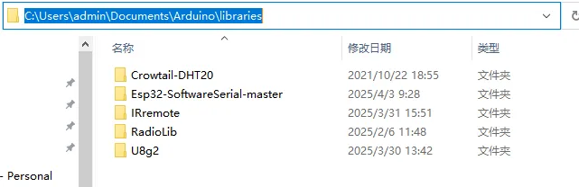
Use the library files we provided.
(Refer to the path for guidance.)