Quick network configuration between the Gateway - ThinkNode and the wireless module of the CrowPanel Advance HMI| ESP32-S3 AI-Powered IPS Touch Screen
1. Network Configuration of Gateway
Configure the gateway's networking method: Three networking methods are available: Ethernet, Wi-Fi, and 4G cellular (applicable only to the 4G version). Here, the Wi-Fi mode is used.
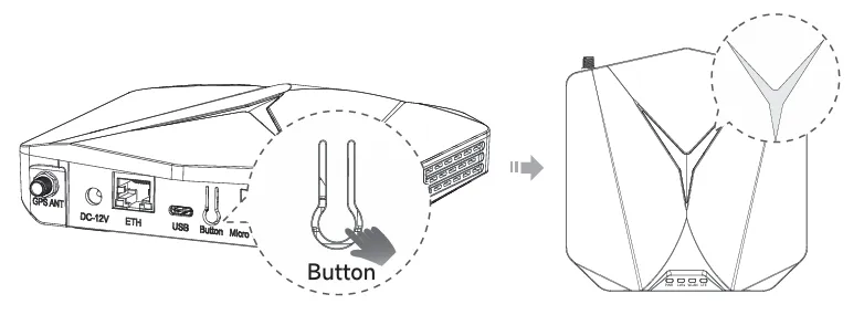
STEP1:Turn on the device's AP hotspot
Press and hold the button for 5 seconds until the top indicator light slowly flashes blue, then it will enter configuration mode.
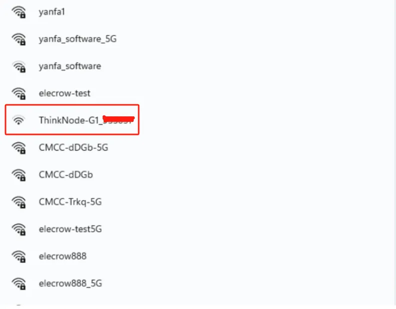
STEP2:Connect to the AP hotspot
The name of the AP hotspot is ThinkNode - G1_XXXXXX (6 - digit MAC address). No password is required, and you can connect directly. Connect your computer or mobile phone to this AP hotspot.
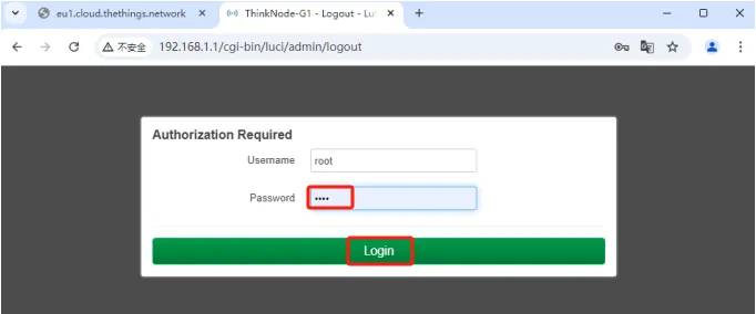
STEP3:Log in to the local console
Enter the IP address (192.168.1.1) in your browser to access the local console. Then, log in with the username "root", enter the password "root", and click the "Login" button.
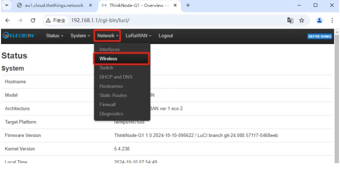
STEP4:Log in to the Luci page, and click Network - Wireless
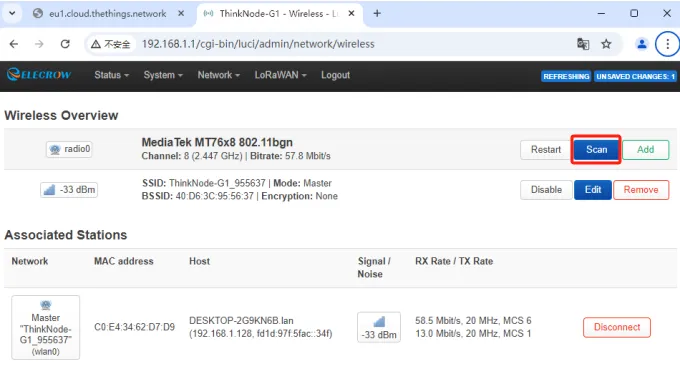
STEP5:Click the "Scan" button to scan for Wi - Fi.
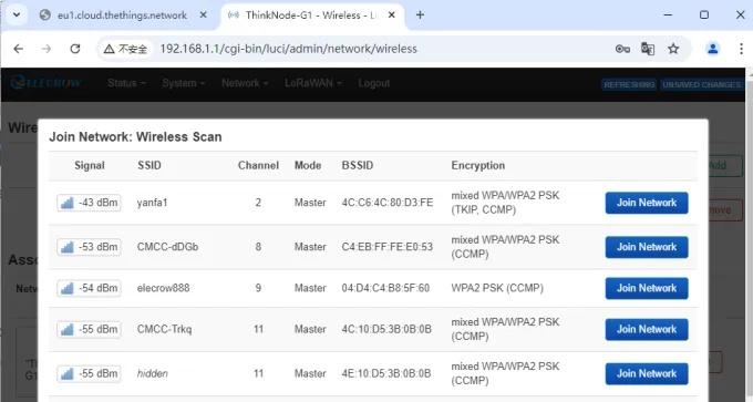
STEP6:Select your Wi - Fi to join the network.
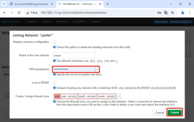
STEP7:Enter the Wi-Fi password, then click "Submit", and save the settings.
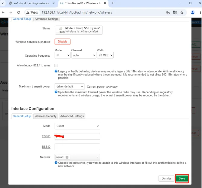
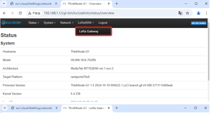
STEP8:Set the gateway's Internet connection method to Wi-Fi.
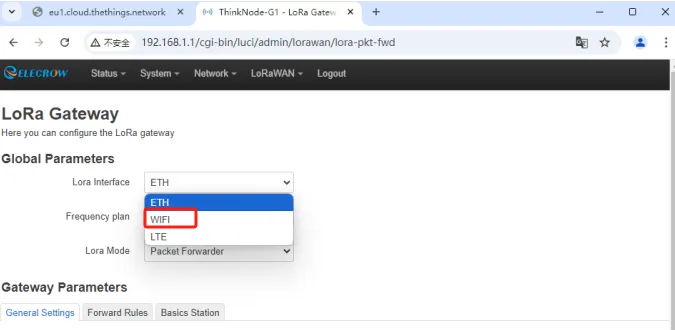
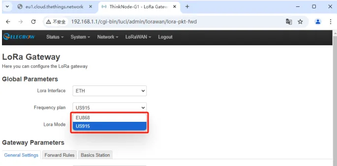
On the Luci interface, click "LoRaWAN" and navigate to the LoRa Gateway interface.
Select the network configuration mode as "WiFi".
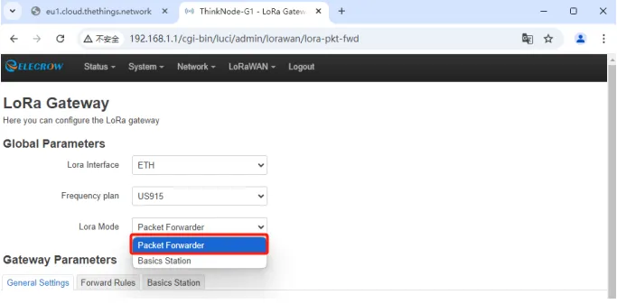
STEP9:Set Mode to Packet Forwarder.
STEP10:Packet Forwarder Settings
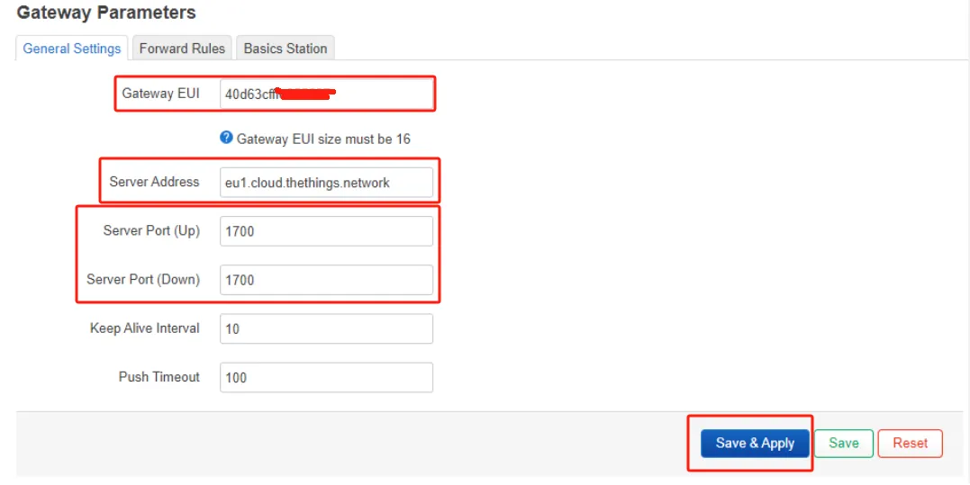
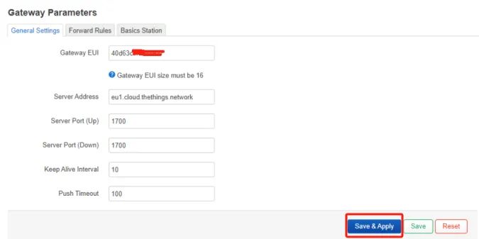
1.Gateway EUI: It will automatically obtain the EUI of the connected gateway.
2.Server address: For the Semtech UDP packet forwarder, use "server-address". "server-address" is the address of The Things Stack deployment.
3.Server Ports (Up/Down): The uplink and downlink ports are typically set to 1700.
Other settings can be left as default or adjusted according to your requirements..
STEP11:Channel Plan Settings
Select the Region and Frequency plans according to the actual situation.
Then click "Save & Apply" to apply your settings.
Note: Remember the Gateway EUI here, which needs to be filled in on the TTN platform later.
Double-click the reset button and wait for the device to restart. If the gateway successfully connects to the Wi-Fi, the WLAN green indicator light will stay on, and the top indicator light will also show a steady green glow.
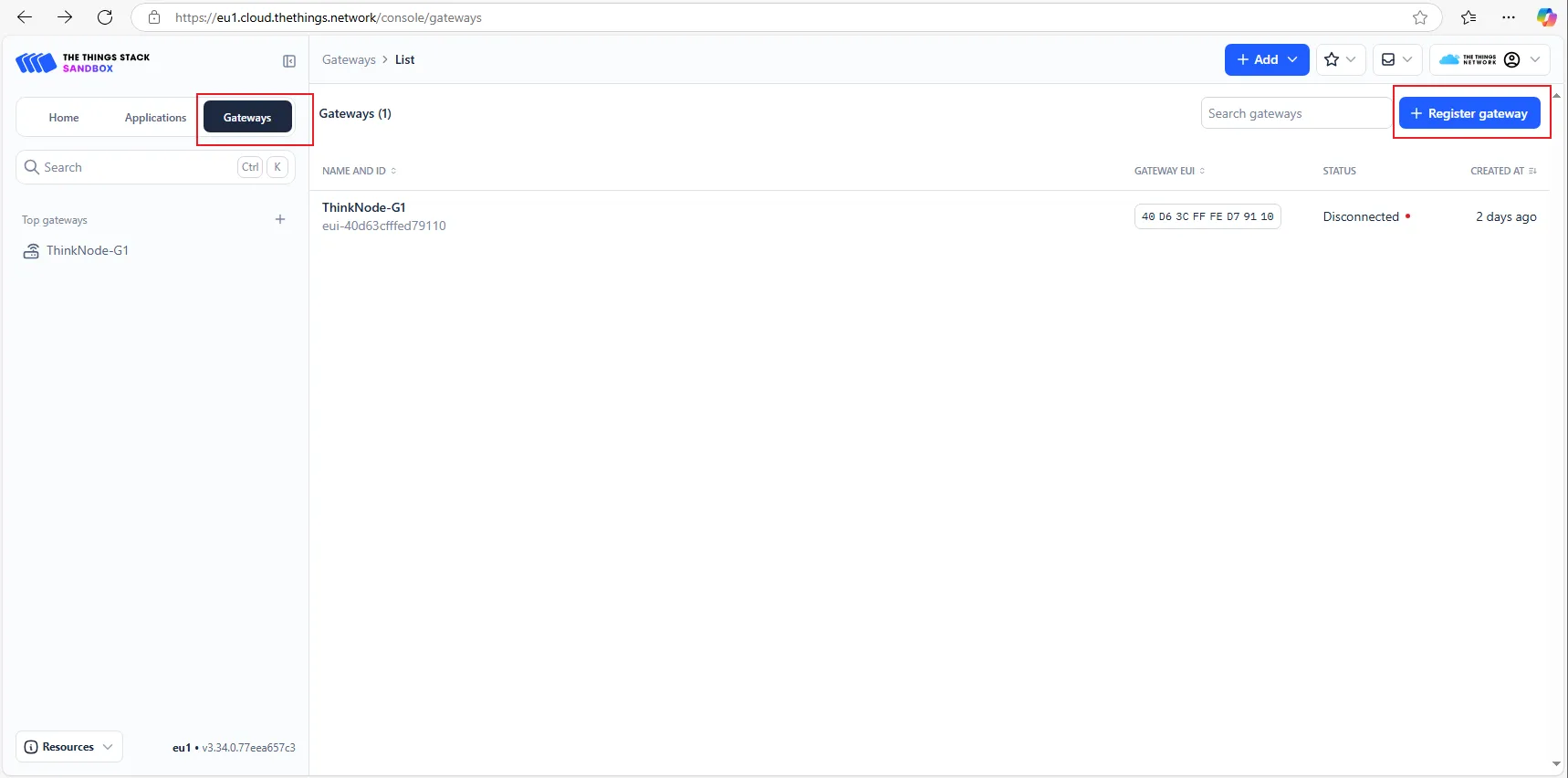
2. Deployment of the G1 gateway on the TTN platform
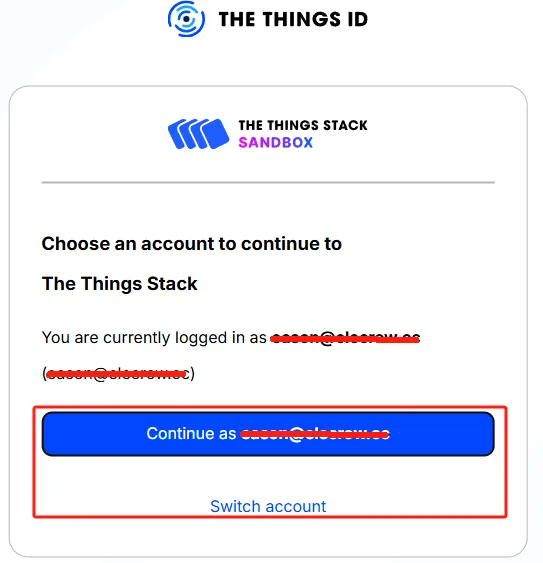
STEP1:Log in to The Things Stack (The Things Network). If you don't have a TTN account, please register first.
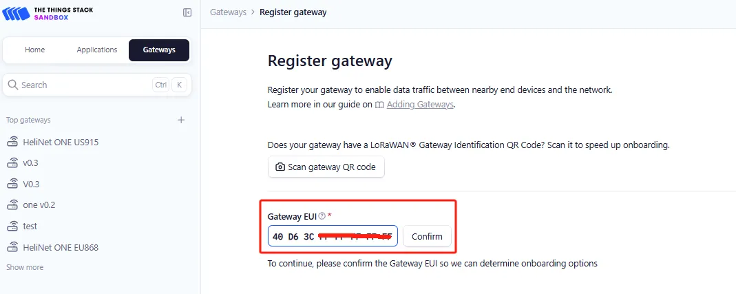
STEP2:Register the gateway, fill in the EUI, and click "confirm".
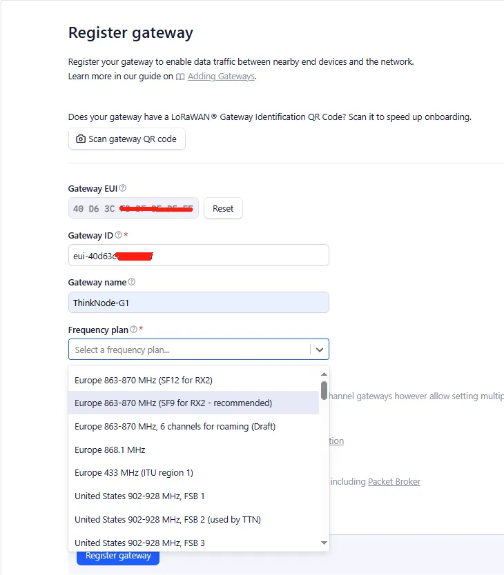
Gateway ID: It typically consists of letters (eui - "Gateway EUI") (The ID must contain only lowercase letters, numbers, and dashes).Note that the letters in "Gateway EUI" must be converted to lowercase.
Gateway Name: The name of the gateway.
Frequency Plan: Select the corresponding frequency according to your gateway version.
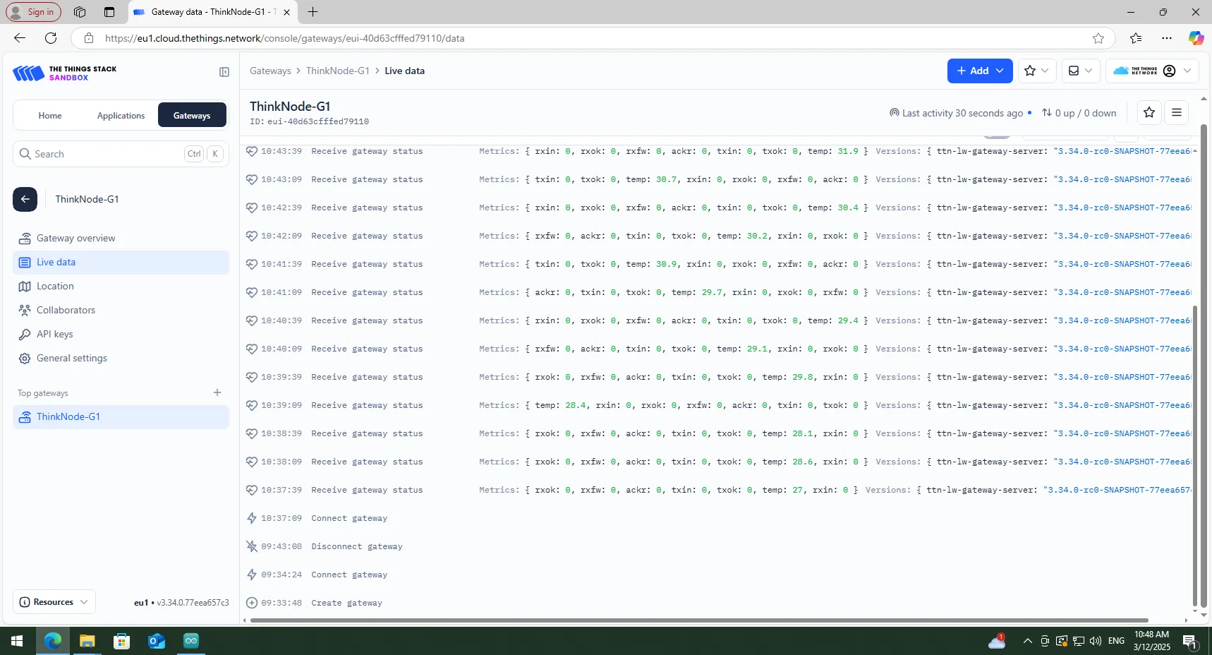
After successful registration, you can view the gateway in the overview.
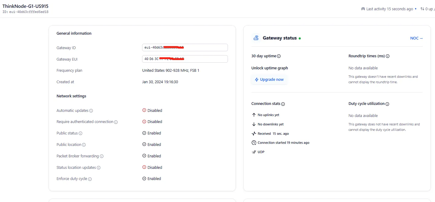
Double - click the gateway settings button and wait for the gateway to restart. The gateway is now connected to TTN as a Packet Forwarder.
3. Create a TTN node application
STEP1:Log in to the registered TTN account.
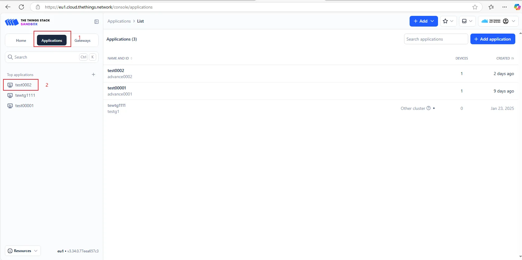
In the TTN server interface, click "Applications".

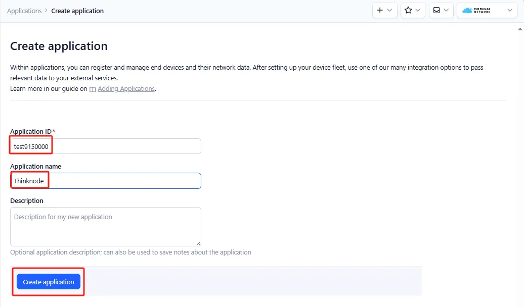
STEP2:Click "Add application" to start adding a node application.
Enter the Application ID and Application name, then click "Create application".
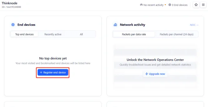
STEP3:Enter the application overview page, click "Register end device" in the lower - left corner to register a new device on the TTN platform.
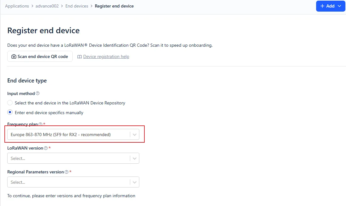
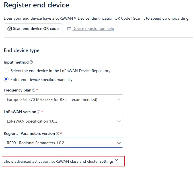
STEP4:In the "Register end device" page, click the "Enter end device specifics manually" option.

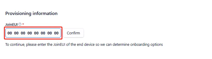
STEP5:Set the Frequency plan, LoRaWAN version, Regional Parameters version, and JoinEUI (APPEUI).
Note: JoinEUI is the same as AppEUI.
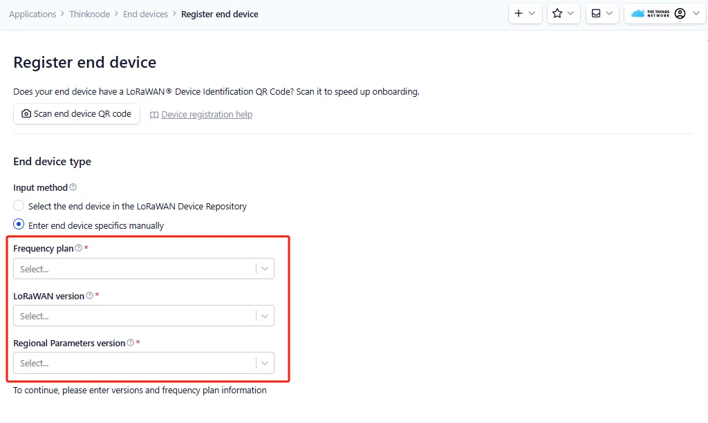
Set the Frequency plan.Note that the frequency band range should be consistent with the one used by the gateway.
Set the LoRaWAN version.
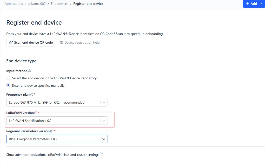
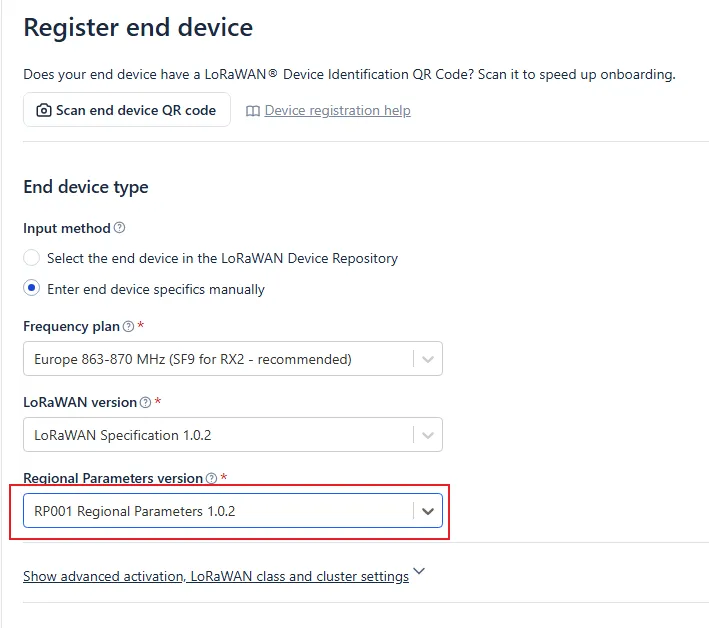
Set the Regional Parameters version.
Set the JoinEUI (APPEUI).
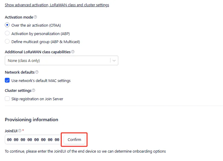
STEP6:Click "Show advanced activation, LoRaWAN class and cluster settings" to configure parameters such as the activation mode and the device operating mode.
· When the activation mode is OTAA
Configure it to OTAA mode (i.e., the default mode).
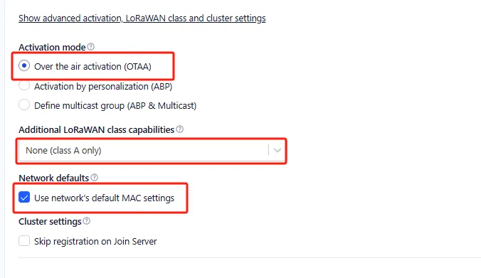
Then click "Confirm".
STEP7:According to the activation mode selected above, configure the corresponding device parameters as shown in the following figure:
Click "Generate" to automatically generate the DevEUI.
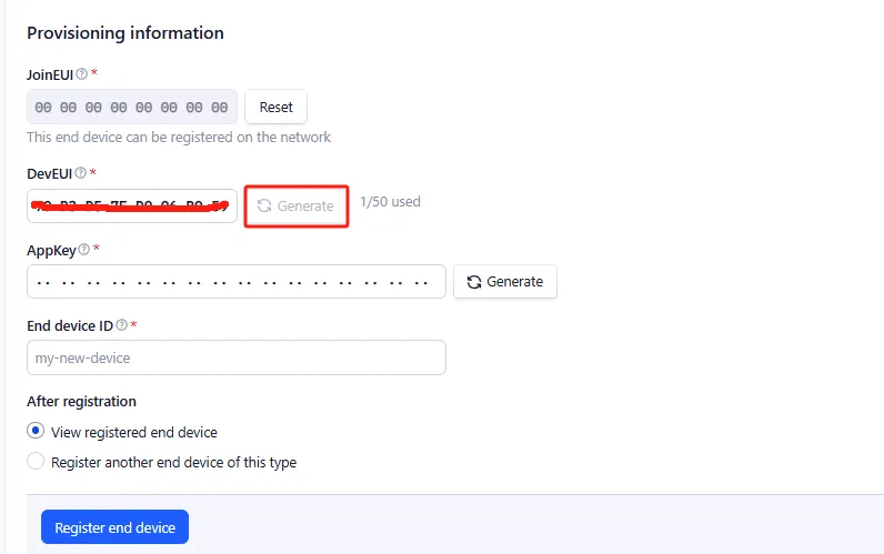
Click "Generate" to automatically generate the AppKey.
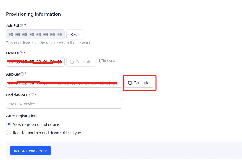
Enter the End device ID.
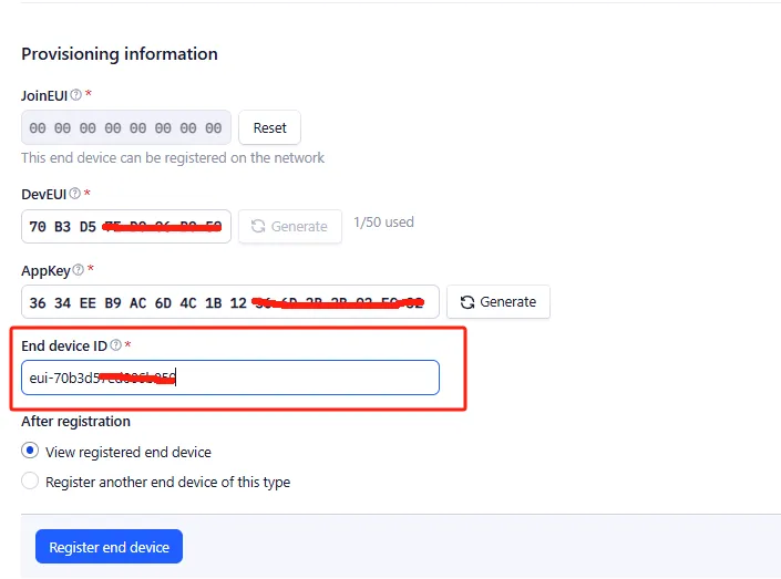
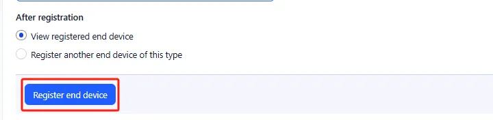
Click "Register end device".
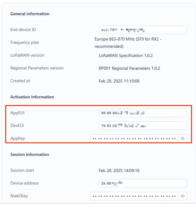
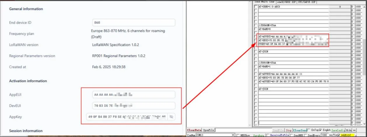
Note: Save the content in the Activation information, which will be used when sending AT commands later.
The OTAA device registration was successful.
Note: Since LoRaWAN does not allow repeated use of network access, when the used DevNonce is ignored, the node can test network access indefinitely.
Click on Application -> Application Name
Click on node name->Settings

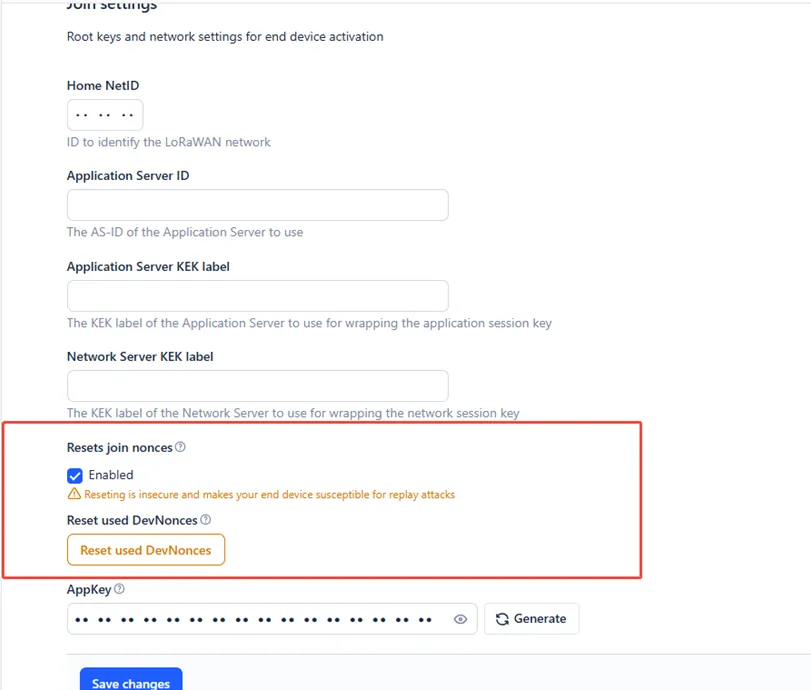
Pull down to the bottom of the page, Select Join Settings.

Enable "Resets join nonces"
Set up network communication between the TTN application node created and the gateway, and upload the communication data between the node and the gateway to the TTN server.
Precondition:
1.A gateway has been created on The Things Network (TTN), and it is connected and operating normally.
2.A node application (OTAA/ABP) corresponding to the frequency band range of the gateway has been created on TTN.
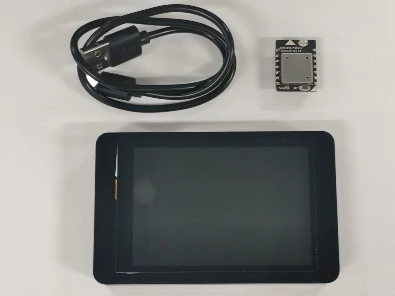
Hardware preparation:
- CrowPanel Advance HMI| ESP32-S3 AI-Powered IPS Touch Screen
- Wireless module-Meshtastic
-
TYPE-C USB cable
Software preparation:
- Prepare the code of the corresponding size
If you are using a 7.0 size, 5.0 size or 4.3 size, please use the code provided in the link below:
If you are using a 3.5 size, please use the code provided in the link below:
If you are using a 2.8 size or 2.4 size, please use the code provided in the link below:
- Prepare the serial port tool
Click the link below to download the serial port tool.
Configure the CrowPanel Advance AI Display for USB - TTL communication mode.
-
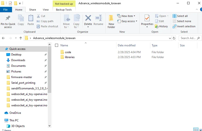
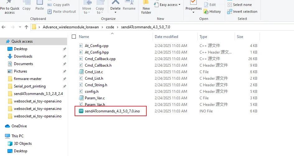
Open the folder attached to this tutorial. Inside the "code" folder are the codes for all sizes, and inside the "libraries" folder are the Arduino library files that are used.
-
First, put the library files into the sketchbook location of Arduino.
Click the link below to download the library files we provide.
Library file link:
If you are not sure where to place the library files and how to configure them properly so that the code can correctly recognize these library files, please refer to the operation steps in the first lesson.
-
Open the corresponding code for the display size using the Arduino IDE (in this course, the code for the large-sized display is used as an example).
-
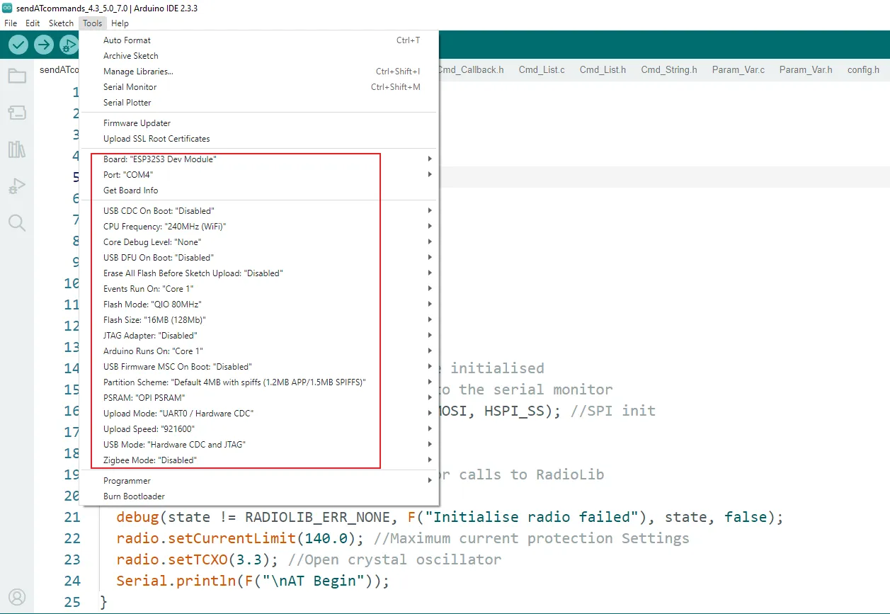
Insert the wireless module into the CrowPanel Advance AI Display, connect it to the computer, and configure the development board.
If you don't know how to configure it, please refer to the tutorial in Lesson 1.
-
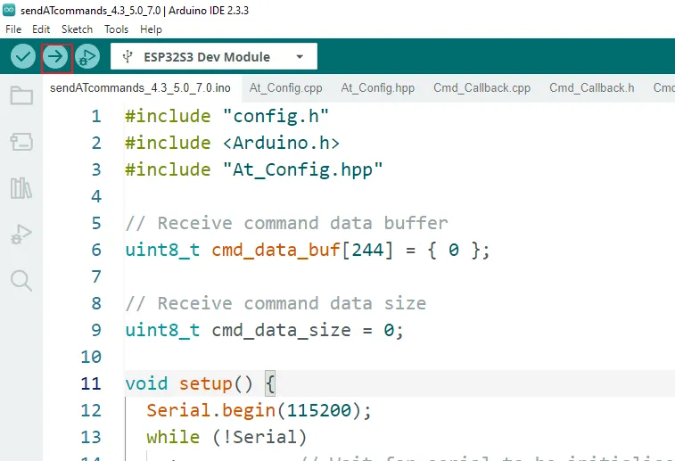
Click "Upload" and wait for the uploading process to be completed.
Note: For the 4.3-inch, 5.0-inch, and 7.0-inch displays, you need to switch the Function Keys to position 01.
Use the SSCOM serial terminal tool to send AT commands to configure the CrowPanel Advance AI Display as a LoRaWAN node for TTN, supporting both OTAA and ABP activation modes.
Then issue additional AT commands to join the LoRaWAN network, register the device on The Things Network (TTN), establish communication with the gateway, and enable real-time uplink of node–gateway data to the TTN server using OTAA mode.
STEP1:Open the SSCOM serial port tool in the serial port assistant. Select the USB COM port recognized by the computer and click "EXT", as shown in the figure below:
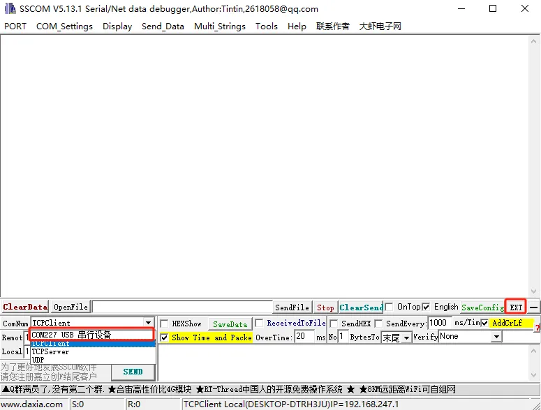
STEP2:Make the following selections and input AT command information on the extended interface of the serial port assistant:
-
Serial port Settings
-
Baud rate:115200
-
Check the option for adding carriage return and line feed in the serial port.
-
Open the serial port and select "Data Terminal Ready": Click "opencom" and only check the "DTR" option.
-
Configuration steps for the node to access the single-channel gateway (send AT commands)
-
Set the network access frequency band of the node: AT+BAND=0. (0 represents the 868 MHz frequency band, 1 represents the 915 MHz frequency band. The node has been configured in the eight-channel mode.)
-
Set the node's DevEui: AT+DEUI=70:B3:D5:7E:D0:06:**** (The red part corresponds to that on the TTN server).
-
Set the node's AppEui: AT+APPEUI=AA:AA:AA:AA:AA:AA:**** (The red part corresponds to that on the TTN server).
-
Set the node's AppKey: AT+APPKEY=49:0F:B4:80:37:F0:5E:6C:5C:B3:24:F5:B5:78:**** (The red part corresponds to that on the TTN server).
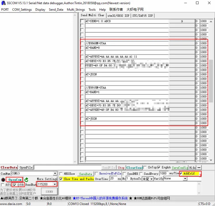
Here, you need to replace the DevEui, AppEui, and AppKey with those in the created OTAA node application.
- Set the node to start joining the network: AT+JOIN. After sending this command, you need to wait for the node to join the network. Only after the node has successfully joined the network can you send the next command, as shown in the following figure: The information printed by the serial port tool after the node has successfully joined the network:
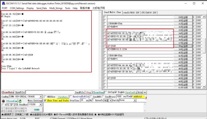
Enter the above AT commands one by one in the extended interface of the serial port assistant. When you enter the "AT+JOIN" command, if the message "Join the LoRaWAN Network" appears, it indicates that the node module has successfully joined the network!
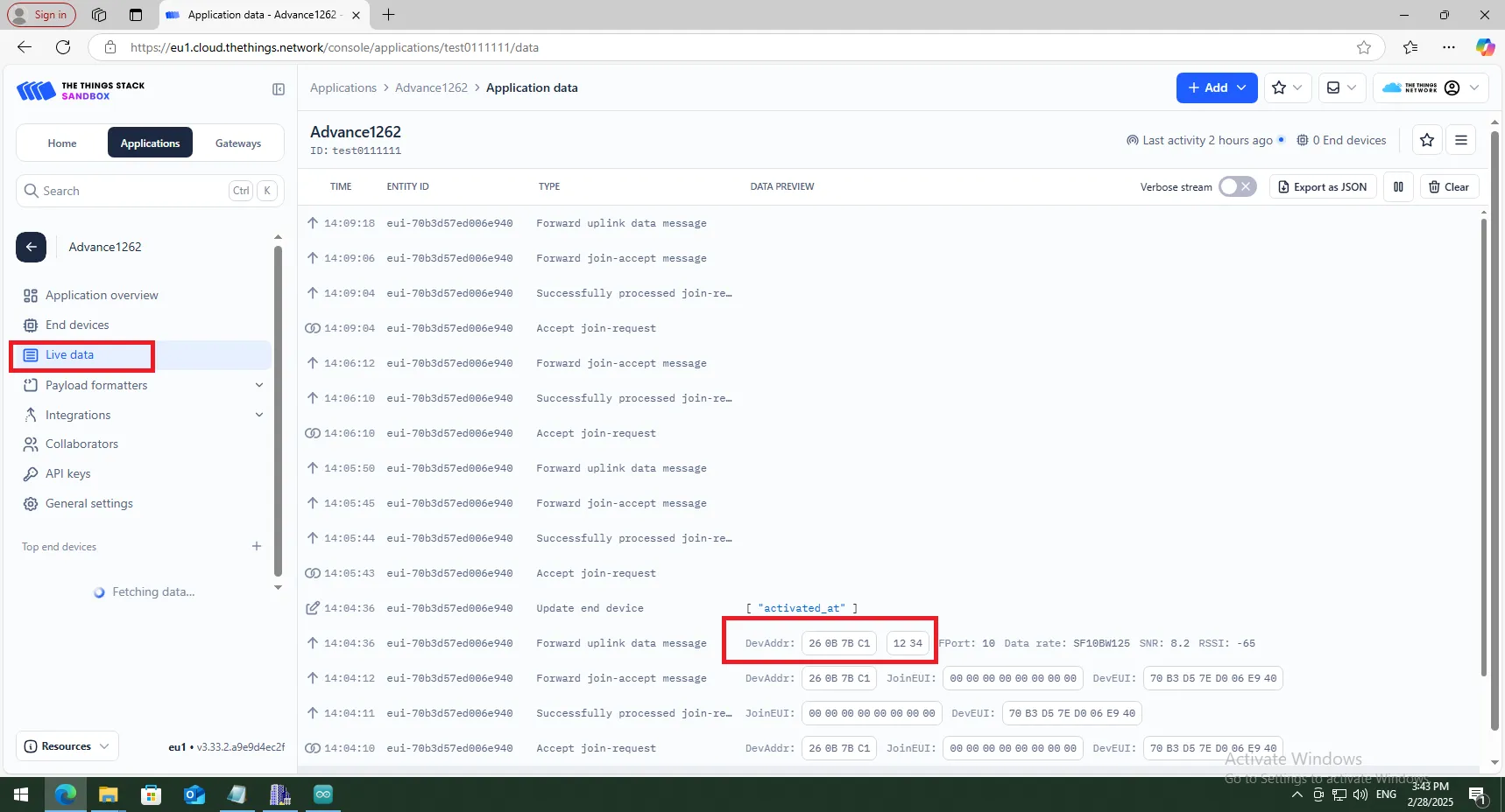
- Start sending data: AT+SEND=10:0:1234 (Parameter description: The last parameter is the data to be sent, and only an even number of data can be sent).
The commands in the SSCOM serial port tool are as follows:
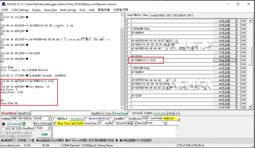
- After sending data using the "AT+SEND=10:0:1234" command, you can view the data "1234" sent by the node in real - time in the "Applications -> Live data" section of the TTN server background.